FRONT SUSPENSION FRONT STABILIZER BAR INSTALLATION
PROCEDURE

 1.INSTALL FRONT STABILIZER BAR SUB-ASSEMBLY
Install the front stabilizer bar sub-assembly to the front frame assembly with the 4 bolts.
- Torque:
- 50 N*m (510 kgf*cm, 37 ft.*lbf)
- NOTICE:
-
Temporarily tighten the bolts in the order of (D), (C) and (B), and then fully tighten the 4 bolts in the order of (A), (B), (C), and (D).
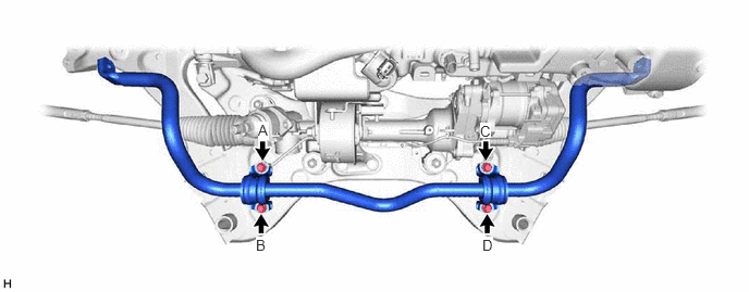
48810
2.INSTALL FRONT STABILIZER LINK ASSEMBLY LH
Install the front stabilizer link assembly LH to the front stabilizer bar sub-assembly with the nut.
- Torque:
- 74 N*m (755 kgf*cm, 55 ft.*lbf)
- NOTICE:
-
Do not damage the boot of the ball joint.
- HINT:
-
If the ball joint turns together with the nut, use a 6 mm hexagon socket wrench to hold the stud bolt.
48820B
3.INSTALL FRONT STABILIZER LINK ASSEMBLY RH
- HINT:
-
Perform the same procedure as for the LH side.
4.INSTALL ENGINE ASSEMBLY WITH TRANSAXLE
for A25A-FXS, A25B-FXS: Click hereEngine / Hybrid System>A25A-FXS, A25B-FXS (ENGINE MECHANICAL)>ENGINE ASSEMBLY>INSTALLATION
for 2GR-FKS: Click hereEngine / Hybrid System>2GR-FKS (ENGINE MECHANICAL)>ENGINE ASSEMBLY>INSTALLATION