Q610 HYBRID TRANSMISSION / TRANSAXLE REAR TRACTION MOTOR INSTALLATION
PROCEDURE

 52383C
1.INSTALL DIFFERENTIAL SUPPORT PROTECTOR
- HINT:
-
Perform this procedure only when replacement of the differential support protector or front differential support assembly is necessary.
Install the differential support protector to the front differential support assembly with the 2 bolts.
- Torque:
- 7.0 N*m (71 kgf*cm, 62 in.*lbf)
G1050C
2.INSTALL REAR TRACTION MOTOR FILLER PLUG
Using a 10 mm hexagon socket wrench, install the rear traction motor filler plug and a new gasket to the rear traction motor with transaxle assembly.
- Torque:
- 39 N*m (398 kgf*cm, 29 ft.*lbf)
52391D
3.INSTALL DIFFERENTIAL SUPPORT
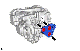
Install the differential support to the rear traction motor with transaxle assembly with the 3 bolts.
- Torque:
- 120 N*m (1224 kgf*cm, 89 ft.*lbf)
- NOTICE:
-
First install the bolt (A).
52380F
4.TEMPORARILY INSTALL FRONT DIFFERENTIAL SUPPORT ASSEMBLY
Temporarily install the front differential support assembly to the rear traction motor with transaxle assembly with 2 new bolts.
5.INSTALL WIRE HARNESS CLAMP BRACKET
Install the wire harness clamp bracket to the rear traction motor with transaxle assembly with the 2 bolts.
- Torque:
- 8.0 N*m (82 kgf*cm, 71 in.*lbf)
G1050
6.INSTALL REAR TRACTION MOTOR WITH TRANSAXLE ASSEMBLY
Using 2 straps, hold the rear traction motor with transaxle assembly.
- CAUTION:
- ·
Do not lift the rear traction motor with transaxle assembly more than necessary.
·When lifting the rear traction motor with transaxle assembly, make sure it is well balanced.
Temporarily install the 2 upper differential mount stoppers, 2 lower differential mount stoppers and rear traction motor with transaxle assembly to the rear suspension member sub-assembly with 3 new bolts.
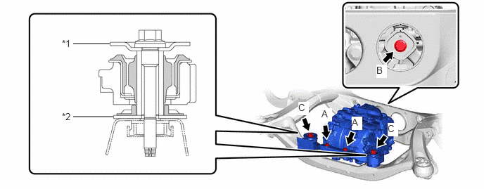
| *1 | Upper Differential Mount Stopper | *2 | Lower Differential Mount Stopper |
Fully tighten the 2 bolts (A).
- Torque:
- 55 N*m (561 kgf*cm, 41 ft.*lbf)
Fully tighten the bolt (B).
- Torque:
- 130 N*m (1326 kgf*cm, 96 ft.*lbf)
- NOTICE:
-
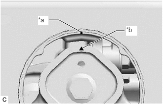 1.031,0.417 1.24,0.417 1.24,0.417 1.698,0.667 true 2.625,0.646 2.448,0.646 2.448,0.646 1.74,1.01 true 0.802,0.333 1.021,0.531 0.219,0.198 10 true *a 2.656,0.542 2.896,0.75 0.24,0.208 10 true *b
*a Inner Cylinder Mark *b Rubber Part Mark
-
After tightening the bolt (B), make sure that the inner cylinder mark and rubber part mark are positioned as shown in the illustration.
Fully tighten the 2 bolts (C).
- Torque:
- 86 N*m (877 kgf*cm, 63 ft.*lbf)
51206A
7.INSTALL REAR SUSPENSION MEMBER SUB-ASSEMBLY
8. PERFORM RESOLVER LEARNING
- NOTICE:
-
If the rear traction motor with transaxle assembly has been replaced, make sure to perform resolver learning.
-
Click hereEngine / Hybrid System>HYBRID / BATTERY CONTROL>MOTOR GENERATOR CONTROL SYSTEM (for 4WD/AWD)>UTILITY