HYBRID / BATTERY CONTROL HYBRID CONTROL SYSTEM(for 2WD) P0ABF2A Hybrid/EV Battery Current Sensor "A" Signal Stuck In Range
DESCRIPTION
Refer to the description for DTC P0ABF11.
Click hereEngine / Hybrid System>HYBRID / BATTERY CONTROL>HYBRID CONTROL SYSTEM (for 2WD)>P0ABF11
| DTC No. | Detection Item | DTC Detection Condition | Trouble Area | MIL | Warning Indicate |
|---|---|---|---|---|---|
| P0ABF2A | Hybrid/EV Battery Current Sensor "A" Signal Stuck In Range | The battery current sensor output is stuck even when the battery voltage changes.
(1 trip detection logic) |
·
Battery voltage sensor ·
HV battery junction block assembly |
Comes on | Master Warning:
Comes on |
| DTC No. | Data List |
|---|---|
| P0ABF2A | Hybrid Battery Current for Hybrid Battery Control*1 |
- HINT:
-
*1: The value of "Hybrid Battery Current for Hybrid Battery Control" usually changes by 4 A or more while the vehicle is accelerating and decelerating.
CONFIRMATION DRIVING PATTERN
- HINT:
-
After repair has been completed, clear the DTC and then check that the vehicle has returned to normal by performing the following All Readiness check procedure.
-
Click hereEngine / Hybrid System>HYBRID / BATTERY CONTROL>HYBRID CONTROL SYSTEM (for 2WD)>UTILITY
Connect the GTS to the DLC3.
Turn the ignition switch to ON and turn the GTS on.
Clear the DTCs (even if no DTCs are stored, perform the clear DTC procedure).
Turn the ignition switch off and wait for 2 minutes or more.
Turn the ignition switch to ON and turn the GTS on.
Drive the vehicle on urban roads for approximately 5 minutes.
Enter the following menus: Powertrain / Hybrid Control / Utility / All Readiness.
Check the DTC judgment result.
- HINT:
- ·
If the judgment result shows NORMAL, the system is normal.
·If the judgment result shows ABNORMAL, the system has a malfunction.
·If the judgment result shows INCOMPLETE, perform driving pattern again.
PROCEDURE
Check and record any HV system DTCs and Freeze Frame Data.
- Powertrain > Hybrid Control > Trouble Codes
- 50001 397
- Result:
Result Proceed to "Only DTC P0ABF2A is output" or "DTC P0ABF2A and DTCs other than those in the following table are output". A DTC P0ABF2A and any of the DTCs in the following table are output at the same time. B
| Relevant DTC | |
|---|---|
| P0A9563 | High Voltage Fuse Accumulated Load History |
| P0ABF11 | Hybrid/EV Battery Current Sensor "A" Circuit Short to Ground |
| P0ABF15 | Hybrid/EV Battery Current Sensor "A" Circuit Short to Auxiliary Battery or Open |
| P0AFC00 | Hybrid/EV Battery Sensor Module |
| P0AFC96 | Hybrid/EV Battery Sensor Module Component Internal Failure |
| P1CBB12 | Hybrid/EV Battery Current Sensor Power Supply Circuit Short to Auxiliary Battery |
| P1CBB14 | Hybrid/EV Battery Current Sensor Power Supply Circuit Short to Ground or Open |
| P308A12 | Hybrid/EV Battery Voltage Sensor All Circuit Short to Auxiliary Battery |
| P0B3B14, P0B4014, P0B4514, P0B4A14, P0B4F14, P0B5414, P0B5914, P0B5E14, P0B6314, P0B6814, P0B6D14, P0B7214, P0B7714 | Hybrid/EV Battery Voltage Sensor "A - M" Circuit Short to Ground or Open |
Turn the ignition switch off.
A
B
Turn the ignition switch to ON.
- NOTICE:
-
Do not turn the ignition switch to ON (READY).
Check the voltage of each HV battery block voltage of "Hybrid Battery Block 1 to 12 Voltage" in the Data List with the ignition switch ON.
- NOTICE:
-
Select "Hybrid Battery Block 1 to 12 Voltage" only. (Do not select any other Data List items.)
- Powertrain > Hybrid Control > Data List
-
Tester Display Hybrid Battery Block 1 Voltage Hybrid Battery Block 2 Voltage Hybrid Battery Block 3 Voltage Hybrid Battery Block 4 Voltage Hybrid Battery Block 5 Voltage Hybrid Battery Block 6 Voltage Hybrid Battery Block 7 Voltage Hybrid Battery Block 8 Voltage Hybrid Battery Block 9 Voltage Hybrid Battery Block 10 Voltage Hybrid Battery Block 11 Voltage Hybrid Battery Block 12 Voltage - 50003 397 161,162,163,164,165,166,167,168,169,170,307,308
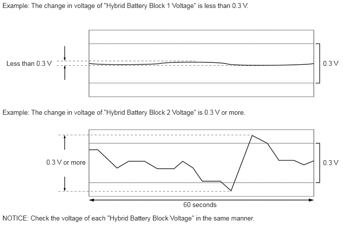
- Specified Condition:
Any "Hybrid Battery Block Voltage" changes by 0.3 V or more, 60 seconds after the ignition switch is turned to ON. (The difference between the maximum and minimum voltage is 0.3 V or more.)
- Result:
Result Proceed to The change in voltage of any "Hybrid Battery Block Voltage" is 0.3 V or more. A Other than above B
Turn the ignition switch off.
A
B