AXLE AND DIFFERENTIAL REAR DIFFERENTIAL CARRIER ASSEMBLY(for Dynamic Torque Control AWD) DISASSEMBLY
CAUTION / NOTICE / HINT
- NOTICE:
- ·
Before installation of each part, thoroughly clean and dry it. Then apply gear oil to it. Do not use alkaline chemicals to clean aluminum parts or rubber parts. Also, do not use non-residue solvent or other cleaning oils to clean O-rings, oil seals or rubber parts.
·Use an overhaul stand as necessary.
PROCEDURE

 41173
1.REMOVE DIFFERENTIAL DISCONNECT COVER
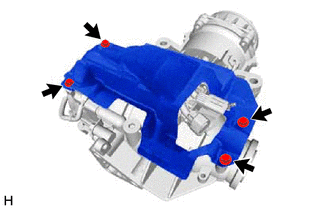
Remove the 4 bolts and differential disconnect cover from the rear differential carrier assembly.
31364D
2.REMOVE CLUTCH CONTROL SOLENOID WIRE
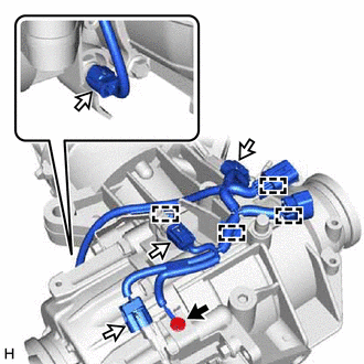

|
Bolt |

|
Connector |
Disconnect the 4 connectors.
Remove the bolt.
Disengage the 4 clamps to remove the clutch control solenoid wire.
3.REMOVE WIRE HARNESS CLAMP BRACKET
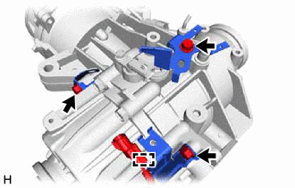
Remove the 3 bolts and 3 wire harness clamp brackets from the rear differential carrier assembly.
Disengage the clamp to disconnect the wire harness.
- NOTICE:
-
Do not damage the wire harness.
89413A
4.REMOVE TRANSMISSION REVOLUTION SENSOR
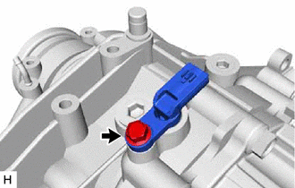
Remove the bolt and transmission revolution sensor from the rear differential carrier assembly.
Remove the O-ring.
89429F
5.REMOVE TEMPERATURE SENSOR
31364D
6.REMOVE CLUTCH CONTROL SOLENOID WIRE
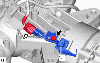
| *a | Cut Area |
|
|
Bolt |
|
|
Connector |
Cut the clutch control solenoid wire as shown in the illustration.
Disconnect the connector.
Remove the bolt and wire harness clamp bracket.
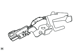
Disengage the clamp to remove the wire harness clamp bracket.
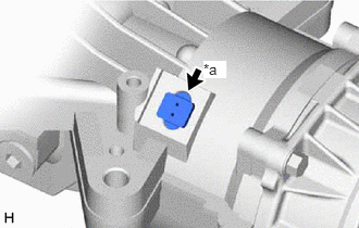
| *a | Grommet |
Disconnect the grommet.
41110K
7.REMOVE REAR DIFFERENTIAL BREATHER PLUG
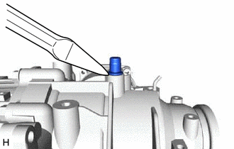
Using a chisel and a hammer, lift the rear differential breather plug slightly.
- NOTICE:
-
Do not damage the contact surface.
Using a screwdriver, remove the rear differential breather plug.
41108A
8.REMOVE REAR DIFFERENTIAL CARRIER COVER PLUG
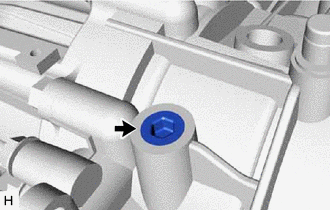
Using an 8 mm hexagon socket wrench, remove the rear differential carrier cover plug.
41181V
9.REMOVE REAR DIFFERENTIAL FILLER PLUG
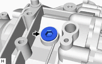
Using a 10 mm hexagon socket wrench, remove the rear differential filler plug and gasket.
41303
10.REMOVE ELECTRO MAGNETIC CONTROL COUPLING SUB-ASSEMBLY
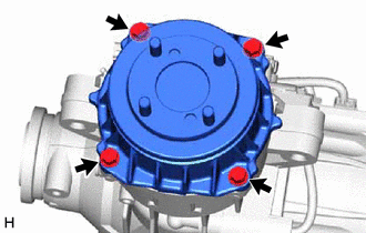
Remove the 4 bolts.
Using a brass bar and a hammer, lightly tap the electro magnetic control coupling sub-assembly to remove it from the rear differential carrier assembly.
- NOTICE:
- ·
Set the brass bar on the ribbed part of the electro magnetic control coupling sub-assembly.
·Do not damage the contact surface.
- HINT:
-
Temporarily install 2 bolts by approximately 5 or 6 threads to prevent the electro magnetic control coupling sub-assembly from falling.
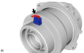
Disconnect the connector.
Remove the O-ring.
41303
11.INSPECT RUNOUT OF ELECTRO MAGNETIC CONTROL COUPLING SUB-ASSEMBLY
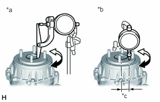
| *a | Vertical Runout |
| *b | Lateral Runout |
| *c | 45.5 mm (1.79 in.) |
Using a dial indicator, measure the runout of the electro magnetic control coupling sub-assembly vertical runout and lateral runout.
- Maximum Runout:
Item Specified Condition Vertical runout 0.070 mm (0.00276 in.) Lateral runout 0.060 mm (0.00236 in.)
- NOTICE:
-
Measure the runout of the electro magnetic control coupling sub-assembly horizontally at a position 45.5 mm (1.79 in.) away from the electro magnetic control coupling sub-assembly.
If the runout is greater than the maximum value, replace the electro magnetic control coupling sub-assembly.
12.REMOVE STUD BOLT
Install 2 service nuts to the stud bolt.
- Recommended Service Nut:
- Thread Diameter:
10 mm (0.394 in.)
- Thread Pitch:
1.0 mm (0.0394 in.)
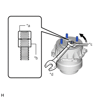
| *a | Upper Nut |
| *b | Lower Nut |
| *c | Turn |
| *d | Hold |
Turn the lower nut and remove the other 3 stud bolts in the same way.
- NOTICE:
-
Prevent foreign matter from entering the electro magnetic control coupling sub-assembly.
- HINT:
-
Lock the lower nut using the upper nut.
If the threads of the electro magnetic control coupling sub-assembly are damaged while removing the stud bolt, replace the electro magnetic control coupling sub-assembly with a new one.
41252D
13.REMOVE REAR DIFFERENTIAL DUST DEFLECTOR (for Front Side)
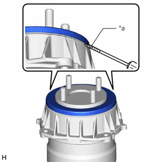
| *a | Protective Tape |
Using a screwdriver, partially separate the rear differential dust deflector.
- NOTICE:
- ·
Separate the rear differential dust deflector to the extent the claws of SST can be inserted.
·Do not damage the end surface of the electro magnetic control coupling sub-assembly.
- HINT:
-
Tape the screwdriver tip before use.
If the end surface of the electro magnetic control coupling sub-assembly is damaged while removing the rear differential dust deflector, replace the electro magnetic control coupling sub-assembly with a new one.
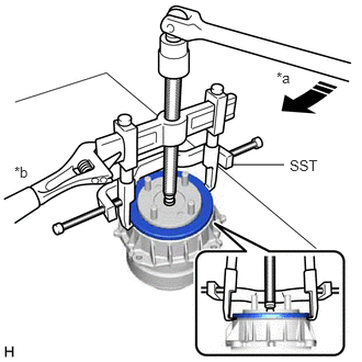
| *a | Turn |
| *b | Hold |
Using SST, remove the rear differential dust deflector as shown in the illustration.
- SST
- 09950-40011 (09951-04020, 09952-04010, 09953-04030, 09954-04010, 09955-04061, 09957-04010, 09958-04011)
- NOTICE:
-
Before using the SST center bolt (09953-04030), apply grease to its threads and tip.
41330M
14.REMOVE TRANSMISSION COUPLING DUST SEAL
41381A
15.REMOVE CONICAL SPRING WASHER
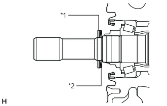
| *1 | Transmission Coupling Spacer |
| *2 | Conical Spring Washer |
Remove the transmission coupling spacer and conical spring washer from the rear differential carrier assembly.
41201C
16.REMOVE REAR DIFFERENTIAL CARRIER OIL SEAL
42340D
17.REMOVE REAR DRIVE SHAFT OIL SEAL LH
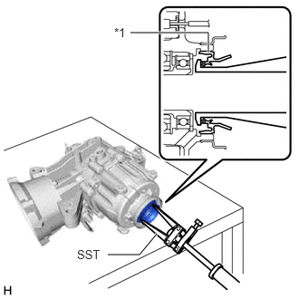
| *1 | Rear Drive Shaft Oil Seal LH |
Using SST, remove the rear drive shaft oil seal LH from the rear differential carrier assembly.
- SST
- 09308-00010
- NOTICE:
-
Do not damage the rear differential carrier assembly.
42330G
18.REMOVE REAR DRIVE SHAFT OIL SEAL RH
- HINT:
-
Use the same procedure as for the LH side.
41252
19.REMOVE REAR DIFFERENTIAL DUST DEFLECTOR (for LH Side)
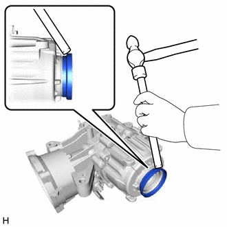
Using a brass bar and a hammer, remove the rear differential dust deflector from the rear differential carrier assembly.
41252
20.REMOVE REAR DIFFERENTIAL DUST DEFLECTOR (for RH Side)
- HINT:
-
Use the same procedure as for the LH side.