AXLE AND DIFFERENTIAL REAR DIFFERENTIAL CARRIER ASSEMBLY(for Dynamic Torque Control AWD) REASSEMBLY
CAUTION / NOTICE / HINT
- NOTICE:
- ·
Before installation of each part, thoroughly clean and dry it. Then apply gear oil to it. Do not use alkaline chemicals to clean aluminum parts or rubber parts. Also, do not use non-residue solvent or other cleaning oils to clean O-rings, oil seals or rubber parts.
·Use an overhaul stand as necessary.
PROCEDURE

 41252
1.INSTALL REAR DIFFERENTIAL DUST DEFLECTOR (for LH Side)
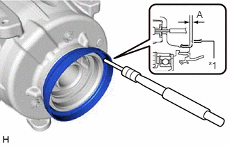
| *1 | Rear Differential Dust Deflector |
Using a 5 mm pin punch and a hammer, install a new rear differential dust deflector to the rear differential carrier assembly.
- Standard Distance (A):
-0.5 to 0.5 mm (-0.00197 to 0.0197 in.)
- NOTICE:
- ·
Install the rear differential dust deflector uniformly.
·Install the rear differential dust deflector straight.
·Do not damage the rear differential dust deflector.
·Do not excessively press in the rear differential dust deflector.
41252
2.INSTALL REAR DIFFERENTIAL DUST DEFLECTOR (for RH Side)
- HINT:
-
Perform the same procedure as for the LH side.
42340D
3.INSTALL REAR DRIVE SHAFT OIL SEAL LH
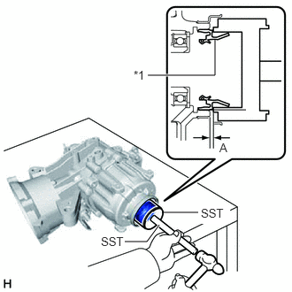
| *1 | Rear Drive Shaft Oil Seal LH |
Using SST and a hammer, install a new rear drive shaft oil seal LH to the rear differential carrier assembly.
- SST
- 09316-10010
09950-70010 (09951-07150)
- Standard Distance (A):
-0.4 to 0.4 mm (-0.00157 to 0.0157 in.)
- NOTICE:
- ·
Install the rear drive shaft oil seal LH uniformly.
·Install the rear drive shaft oil seal LH straight.
·Do not damage the rear drive shaft oil seal LH.
·Do not damage the rear differential dust deflector.
·Do not excessively press in the rear drive shaft oil seal LH.
·Make sure to install the rear drive shaft oil seal LH as specified, otherwise a malfunction such as an oil leak may occur.
Apply a light coat of MP grease to the lip of the rear drive shaft oil seal LH.
42330G
4.INSTALL REAR DRIVE SHAFT OIL SEAL RH
- HINT:
-
Use the same procedure as for the LH side.
41201C
5.INSTALL REAR DIFFERENTIAL CARRIER OIL SEAL
41330M
6.INSTALL TRANSMISSION COUPLING DUST SEAL
41252D
7.INSTALL REAR DIFFERENTIAL DUST DEFLECTOR (for Front Side)
Temporarily install a new rear differential dust deflector.
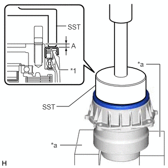
| *1 | Rear Differential Dust Deflector |
| *a | V-block |
Using SST, V-blocks and a press, install the rear differential dust deflector to the electro magnetic control coupling sub-assembly.
- SST
- 09223-56010
- Standard Distance (A):
5.5 to 6.1 mm (0.217 to 0.240 in.)
- NOTICE:
- ·
Make sure that the electro magnetic control coupling sub-assembly is supported as shown in the illustration.
·Install the rear differential dust deflector uniformly.
·Install the rear differential dust deflector straight.
·Do not damage the end surface of the electro magnetic control coupling sub-assembly.
·Do not excessively press in the rear differential dust deflector.
If the end surface of the electro magnetic control coupling sub-assembly is damaged while installing the rear differential dust deflector, replace the electro magnetic control coupling sub-assembly with a new one.
41381A
8.INSTALL CONICAL SPRING WASHER
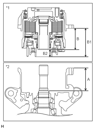
| *1 | Electro Magnetic Control Coupling Sub-assembly |
| *2 | Rear Differential Carrier Assembly |
Using a vernier caliper and precision straightedge, measure dimensions (B1) and (B2) of the electro magnetic control coupling sub-assembly.
Calculate dimension (B) by subtracting dimension (B2) from (B1).
- HINT:
- ·
Dimension (B) = Dimension (B1) - Dimension (B2)
·Dimension (B1) is the distance from the installation surface of the electro magnetic control coupling sub-assembly to the edge of the bearing.
Using a vernier caliper and precision straightedge, measure dimension (A) of the rear differential carrier assembly.
- HINT:
-
Dimension (A) is the distance from the installation surface of the rear differential carrier assembly to the edge of the differential drive pinion.
Select a transmission coupling spacer and install it.
- NOTICE:
-
Keep the transmission coupling spacer free of oil and foreign matter.
- HINT:
-
Transmission coupling spacer thickness = Dimension (A) - Dimension (B) - 1.6
- Transmission Coupling Spacer:
Part No. Thickness 90564-25045 1.79 to 1.81 mm (0.0705 to 0.0713 in.) 90564-25046 1.89 to 1.91 mm (0.0744 to 0.0752 in.) 90564-25047 1.99 to 2.01 mm (0.0783 to 0.0791 in.) 90564-25048 2.09 to 2.11 mm (0.0823 to 0.0831 in.) 90564-25049 2.19 to 2.21 mm (0.0862 to 0.0870 in.) 90564-25050 2.29 to 2.31 mm (0.0902 to 0.0909 in.) 90564-25051 2.39 to 2.41 mm (0.0941 to 0.0949 in.) 90564-25052 2.49 to 2.51 mm (0.0980 to 0.0988 in.) 90564-25053 2.59 to 2.61 mm (0.1020 to 0.1028 in.) 90564-25054 2.69 to 2.71 mm (0.1059 to 0.1067 in.) 90564-25055 2.79 to 2.81 mm (0.1098 to 0.1106 in.) 90564-25056 2.89 to 2.91 mm (0.1138 to 0.1146 in.) 90564-25057 2.99 to 3.01 mm (0.1177 to 0.1185 in.)
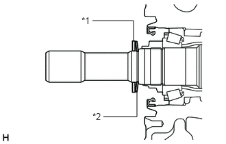
| *1 | Transmission Coupling Spacer |
| *2 | Conical Spring Washer |
Install the transmission coupling spacer and conical spring washer to the rear differential carrier assembly as shown in the illustration.
- HINT:
-
Make sure to install the conical spring washer with the concave side facing the front of the vehicle.
41303
9.INSTALL ELECTRO MAGNETIC CONTROL COUPLING SUB-ASSEMBLY
Apply gear oil to a new O-ring.
Install the O-ring to the electro magnetic control coupling sub-assembly.
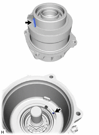
Align the pin and hole, and install the electro magnetic control coupling sub-assembly with the 4 bolts.
- Torque:
- 19.6 N*m (200 kgf*cm, 14 ft.*lbf)
- NOTICE:
- ·
Do not damage the rear differential carrier oil seal.
·Do not damage the contact surface of the rear differential carrier assembly and electro magnetic control coupling sub-assembly.
If the contact surface of the rear differential carrier assembly or electro magnetic control coupling sub-assembly is damaged while installing the electro magnetic control coupling sub-assembly, replace the rear differential carrier assembly or electro magnetic control coupling sub-assembly with a new one.
10.INSTALL STUD BOLT
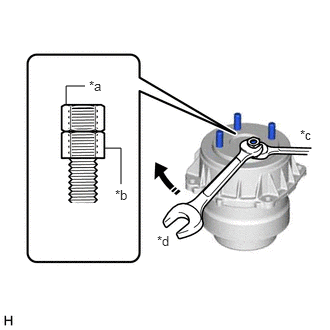
| *a | Upper Nut |
| *b | Lower Nut |
| *c | Hold |
| *d | Turn |
Temporarily install the 4 stud bolts to the electro magnetic control coupling sub-assembly.
- NOTICE:
- ·
Make sure to install the longer bolt on the electro magnetic control coupling sub-assembly side.
·Prevent foreign matter from entering the electro magnetic control coupling sub-assembly.
Install 2 service nuts to the stud bolt.
- Recommended Service Nut:
- Thread Diameter:
10 mm (0.394 in.)
- Thread Pitch:
1.0 mm (0.0394 in.)
- HINT:
-
Lock the upper nut using the lower nut.
If the threads of the electro magnetic control coupling sub-assembly are damaged while installing the stud bolt, replace the electro magnetic control coupling sub-assembly with a new one.
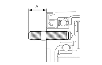
Turn the upper nut and tighten the other 3 stud bolts to the electro magnetic control coupling sub-assembly in the same way.
- Torque:
- 9.8 N*m (100 kgf*cm, 87 in.*lbf)
- Standard Distance (A):
22.55 to 25.85 mm (0.888 to 1.017 in.)
41181V
11.INSTALL REAR DIFFERENTIAL FILLER PLUG
Using a 10 mm hexagon socket wrench, install a new gasket and the rear differential filler plug.
- Torque:
- 39 N*m (398 kgf*cm, 29 ft.*lbf)
41108A
12.INSTALL REAR DIFFERENTIAL CARRIER COVER PLUG
Using an 8 mm hexagon socket wrench, install a new rear differential carrier cover plug.
- Torque:
- 30 N*m (306 kgf*cm, 22 ft.*lbf)
41110K
13.INSTALL REAR DIFFERENTIAL BREATHER PLUG
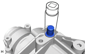
Using a 14 mm deep socket wrench and a hammer, install a new rear differential breather plug to the rear differential carrier assembly.
- HINT:
-
Tap in the rear differential breather plug until it sits flush with the rear differential carrier assembly.
31364D
14.INSTALL CLUTCH CONTROL SOLENOID WIRE
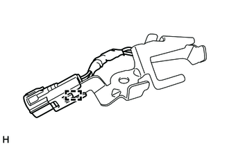
Engage the clamp to install a new clutch control solenoid wire to the wire harness clamp bracket.
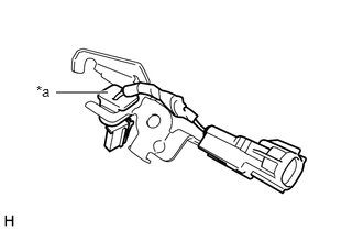
| *a | Grommet |
Set the grommet to the wire harness clamp bracket as shown in the illustration.
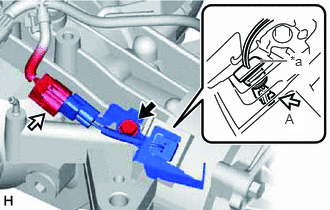
| *a | Grommet |

|
Bolt |

|
Connector |
Connect the 2 connectors and grommet.
- NOTICE:
-
Make sure to push down on the grommet to connect the connector (A) and to securely install the grommet.
Install the wire harness clamp bracket with the bolt.
- Torque:
- 5.4 N*m (55 kgf*cm, 48 in.*lbf)
89429F
15.INSTALL TEMPERATURE SENSOR
89413A
16.INSTALL TRANSMISSION REVOLUTION SENSOR
Apply gear oil to a new O-ring.
Install the O-ring to the transmission revolution sensor.
Install the transmission revolution sensor to the rear differential carrier assembly with the bolt.
- Torque:
- 6.5 N*m (66 kgf*cm, 58 in.*lbf)
17.INSTALL WIRE HARNESS CLAMP BRACKET
Engage the clamp to connect the wire harness.
- NOTICE:
-
Do not damage the wire harness.
Install the 3 wire harness clamp brackets with 3 bolts to the rear differential carrier assembly.
- Torque:
- 19.6 N*m (200 kgf*cm, 14 ft.*lbf)
31364D
18.INSTALL CLUTCH CONTROL SOLENOID WIRE
Engage the 4 clamps to install the clutch control solenoid wire.
Install the bolt.
- Torque:
- 5.4 N*m (55 kgf*cm, 48 in.*lbf)
Connect the 4 connectors.
41173
19.INSTALL DIFFERENTIAL DISCONNECT COVER
Install the 4 bolts and differential disconnect cover to the rear differential carrier assembly.
- Torque:
- 6.5 N*m (66 kgf*cm, 58 in.*lbf)