GF2A TRANSFER / 4WD / AWD DYNAMIC TORQUE VECTORING AWD SYSTEM C13E01C 4WD/AWD Clutch "B" Position Sensor Circuit Range/Performance Circuit Voltage Out of Range
DESCRIPTION
| DTC No. | Detection Item | DTC Detection Condition | Trouble Area | Warning Indicate | Memory |
|---|---|---|---|---|---|
| C13E01C | 4WD/AWD Clutch "B" Position Sensor Circuit Range/Performance Circuit Voltage Out of Range | ·
The No. 2 4 wheel drive position switch power source voltage malfunction continues for 1.2 seconds or more ·
The TNR terminal voltage is less than 0.63 V or higher than 4.5 V for 1.2 seconds or more |
·
Wire harness or connector ·
No. 2 4 wheel drive position switch ·
4WD ECU assembly |
Displayed | Yes |
| Vehicle Condition | ||||
|---|---|---|---|---|
| Pattern 1 | Pattern 2 | Pattern 3 | ||
| Diagnosis Condition | - | - | - | - |
| Malfunction Status | The No. 2 4 wheel drive position switch power source voltage malfunction | ○ | - | - |
| The TNR terminal voltage is less than 0.63 V | - | ○ | - | |
| The TNR terminal voltage is higher than 4.5 V | - | - | ○ | |
| Detection Time | 1.2 seconds or more | 1.2 seconds or more | 1.2 seconds or more | |
| Number of Trips | 1 trip | 1 trip | 1 trip | |
- HINT:
-
DTC will be stored when conditions for either of the patterns in the table above are met.
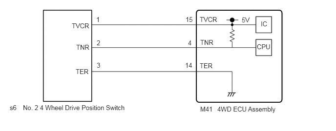
WIRING DIAGRAM
CAUTION / NOTICE / HINT
- NOTICE:
- ·
When the 4WD ECU assembly is replaced, before removing the 4WD ECU assembly, it is necessary to perform ECU Data Save to save the original 4WD ECU assembly information.
Click hereDrivetrain>GF2A (TRANSFER / 4WD / AWD)>DYNAMIC TORQUE VECTORING AWD SYSTEM>CALIBRATION
·After performing repairs, clear the DTCs and check that the DTCs are not output again.
Click hereDrivetrain>GF2A (TRANSFER / 4WD / AWD)>DYNAMIC TORQUE VECTORING AWD SYSTEM>DTC CHECK / CLEAR
PROCEDURE
Remove the No. 2 4 wheel drive position switch.
Connect 3 1.5 V dry batteries in series.
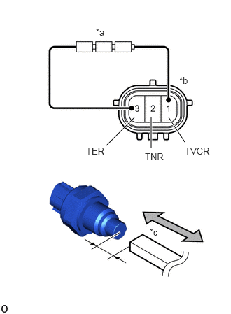
| *a | Dry Batteries |
| *b | Component without harness connected
(No. 2 4 Wheel Drive Position Switch) |
| *c | Piece of Metal |
Connect a positive (+) lead from the batteries to terminal 1 (TVCR) and a negative (-) lead to terminal 3 (TER).
Move a piece of metal close to the edge of the No. 2 4 wheel drive position switch, and then move it away and check that the resistance changes.
Measure the resistance according to the value(s) in the table below.
- Standard Resistance:
Tester Connection Condition Specified Condition 2 (TNR) - 3 (TER) Low (Move piece of metal away) 150 to 620 Ω 2 (TNR) - 3 (TER) High (Move piece of metal closer) 1.1 to 6.2 kΩ
- Result:
Proceed to OK NG
OK
NG
Disconnect the M41 4WD ECU assembly connector.
Disconnect the s6 No. 2 4 wheel drive position switch connector.
Measure the resistance according to the value(s) in the table below.
- Standard Resistance:
Tester Connection Condition Specified Condition M41-4 (TNR) - s6-2 (TNR) Always Below 1 Ω M41-15 (TVCR) - s6-1 (TVCR) Always Below 1 Ω M41-14 (TER) - s6-3 (TER) Always Below 1 Ω M41-4 (TNR) or s6-2 (TNR) - Body ground and other terminals Always 10 kΩ or higher M41-15 (TVCR) or s6-1 (TVCR) - Body ground and other terminals Always 10 kΩ or higher M41-14 (TER) or s6-3 (TER) - Body ground and other terminals Always 10 kΩ or higher
Measure the voltage according to the value(s) in the table below.
- Standard Voltage:
Tester Connection Condition Specified Condition M41-14 (TER) or s6-3 (TER) - Body ground Always Below 1 V
- Result:
Proceed to OK NG
OK
NG