DRIVE SHAFT / PROPELLER SHAFT PROPELLER SHAFT ASSEMBLY REMOVAL
CAUTION / NOTICE / HINT
The necessary procedures (adjustment, calibration, initialization, or registration) that must be performed after parts are removed and installed, or replaced during propeller with center bearing shaft assembly removal/installation are shown below.
| Replaced Part or Performed Procedure | Necessary Procedure | Effect/Inoperative Function when Necessary Procedure not Performed | Link |
|---|---|---|---|
| Gas leaks from exhaust system | Inspection After Repair | ·
Poor idle, etc. ·
Engine start function, etc. |
( ) |
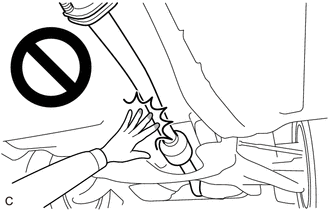
- CAUTION:
-
-
To prevent burns, do not touch the engine, exhaust pipe or other high temperature components while the engine is hot.
PROCEDURE

 17430
1.REMOVE TAIL EXHAUST PIPE ASSEMBLY
17420
2.REMOVE CENTER EXHAUST PIPE ASSEMBLY (TWC: Rear Catalyst)
58720B
3.REMOVE ENGINE SERVICE COVER ASSEMBLY
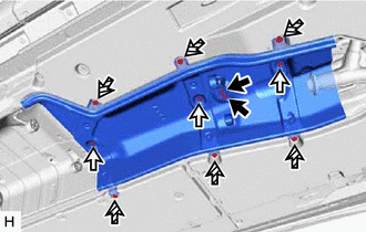

|
Bolt (A) |

|
Nut |

|
Bolt (B) |
Remove the 2 bolts (A) and No. 1 exhaust pipe support bracket.
Remove the 6 bolts (B), 3 nuts and engine service cover assembly from the vehicle body.
58043
4.REMOVE REAR MAIN MUFFLER HEAT INSULATOR SUB-ASSEMBLY
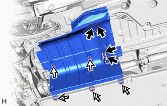
|
|
Bolt (A) |
|
|
Nut |
|
|
Bolt (B) |
Remove the 4 bolts (A), No. 3 exhaust pipe support bracket and No. 4 exhaust pipe support bracket.
Remove the 3 bolts (B), 2 nuts and rear main muffler heat insulator sub-assembly from the vehicle body.
37100
5.REMOVE PROPELLER WITH CENTER BEARING SHAFT ASSEMBLY
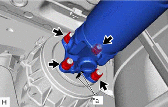
| *a | Matchmark |
Put matchmarks on the rear differential carrier assembly and propeller with center bearing shaft assembly.
Remove the 4 nuts and 4 washers.
Using a brass bar and a hammer, separate the propeller with center bearing shaft assembly.
- NOTICE:
-
Use wire or an equivalent tool to keep the propeller with center bearing shaft assembly.
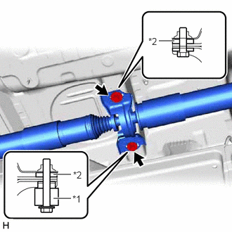
| *1 | Center Support Bearing Damper |
| *2 | Center No. 2 Support Bearing Washer |
Remove the bolt, center support bearing damper and 2 center No. 2 support bearing washers (for rear side).
- NOTICE:
-
When removing the bolt, center support bearing damper and center No. 2 support bearing washers, do not apply excessive force to the universal joint.
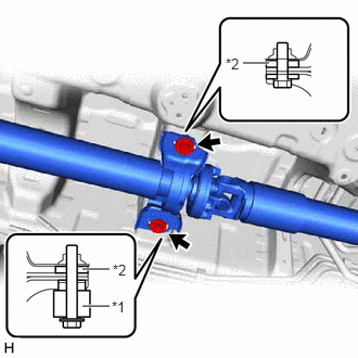
| *1 | Center Support Bearing Damper |
| *2 | Center No. 2 Support Bearing Washer |
Remove the bolt, center support bearing damper and 2 center No. 2 support bearing washers (for front side).
- NOTICE:
-
When removing the bolt, center support bearing damper and center No. 2 support bearing washers, do not apply excessive force to the universal joint.
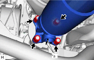
| *a | Matchmark |
Put matchmarks on the transfer assembly and propeller with center bearing shaft assembly.
Remove the 4 nuts, 4 washers and propeller with center bearing shaft assembly from the transfer assembly.
- NOTICE:
- ·
When removing the propeller with center bearing shaft assembly, do not apply excessive force to the universal joint.
·During and after the removal of the propeller with center bearing shaft assembly, keep the universal joint angle straight (within 15 degrees).