A25A-FXS, A25B-FXS ENGINE CONTROL ECM INSTALLATION
PROCEDURE

 89668
1.INSTALL NO. 2 ECM BRACKET
Install the No. 2 ECM bracket to the ECM with the 2 screws.
- Torque:
- 4.5 N*m (46 kgf*cm, 40 in.*lbf)
89667E
2.INSTALL NO. 1 ECM BRACKET
Install the No. 1 ECM bracket to the ECM with the 2 screws.
- Torque:
- 4.5 N*m (46 kgf*cm, 40 in.*lbf)
89661
3.INSTALL ECM
Install the ECM with the bolt and 2 nuts.
- Torque:
- 8.0 N*m (82 kgf*cm, 71 in.*lbf)
- NOTICE:
-
If the ECM has been struck or dropped, replace it.
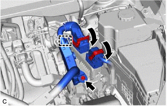
Engage the clamp.
Install the engine wire to the No. 1 ECM bracket with the bolt.
- Torque:
- 10 N*m (102 kgf*cm, 7 ft.*lbf)
Connect the 2 ECM connectors and rotate the 2 levers to lock them.
- NOTICE:
- ·
When connecting the ECM connectors, make sure that the connecting parts of the ECM connectors are free of dirt, water and other foreign matter.
·Be sure to securely connect the ECM connectors.
4.CONNECT CABLE TO NEGATIVE AUXILIARY BATTERY TERMINAL
58441L
5.INSTALL BATTERY SERVICE HOLE COVER
6.PERFORM INITIALIZATION
7. GPF DEPOSITION VALUES (w/ Differential Pressure Sensor)
- NOTICE:
-
Before replacing the ECM, store the volumes of accumulated ash (metal oxide) and PM (Particulate Matter). After replacing the ECM, write the volumes of accumulated ash and PM to the new ECM.
-
Click hereEngine / Hybrid System>A25A-FXS, A25B-FXS (ENGINE CONTROL)>SFI SYSTEM>REGISTRATION