METER / GAUGE / DISPLAY HEADUP DISPLAY SYSTEM B132187 Lost Communication with EMV Missing Message
DESCRIPTION
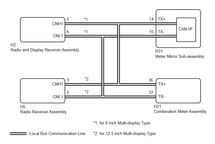
After the meter mirror sub-assembly has started, the meter mirror sub-assembly attempts to detect the radio and display receiver assembly*1 or radio receiver assembly*2 by performing communication via local bus.
This DTC is stored when the radio and display receiver assembly*1 or radio receiver assembly*2 has been detected but communication between the meter mirror sub-assembly and radio and display receiver assembly*1 or radio receiver assembly*2 is interrupted.
*1: for 8 Inch Multi-display Type
*2: for 12.3 Inch Multi-display Type
| DTC No. | Detection Item | DTC Detection Condition | Trouble Area |
|---|---|---|---|
| B132187 | Lost Communication with EMV Missing Message | Diagnosis Condition (for 8 Inch Multi-display Type):
·
The meter mirror sub-assembly has started ·
The radio and display receiver assembly has started Diagnosis Condition (for 12.3 Inch Multi-display Type): ·
The meter mirror sub-assembly has started ·
The radio receiver assembly has started Malfunction Status (for 8 Inch Multi-display Type): After the radio and display receiver assembly is detected, communication via local bus is interrupted Malfunction Status (for 12.3 Inch Multi-display Type): After the radio receiver assembly is detected, communication via local bus is interrupted Malfunction Time: 30 seconds or more |
·
Radio and display receiver assembly ·
Radio receiver assembly ·
Harness or connector ·
Meter mirror sub-assembly |
WIRING DIAGRAM
PROCEDURE
Choose the model to be inspected.
- Result:
Result Proceed to w/o Navigation System A w/ Navigation System B
A
B
Check if audio and visual system DTCs are output.
- Body Electrical > Navigation System > Trouble Codes
- 50001 212
- Result:
Result Proceed to DTCs are not output A DTCs are output B
A
B
Click hereAudio / Visual / Telematics>AUDIO / VIDEO>AUDIO AND VISUAL SYSTEM>DIAGNOSTIC TROUBLE CODE CHART
Check if meter / gauge system DTCs are output.
- Body Electrical > Combination Meter > Trouble Codes
- 50001 122
- HINT:
- ·
If DTC B132187 is output from the headup display system and is not output from the meter / gauge system, it can be suspected that the meter mirror sub-assembly has an internal malfunction.
·If DTC B132187 is output from the meter / gauge system and is not output from the audio and visual system, it can be suspected that the radio and display receiver assembly has an internal malfunction.
- Result:
Result Proceed to DTC B132187 is not output A DTC B132187 is output B
A
B
Check if navigation system DTCs are output.
- Body Electrical > Navigation System > Trouble Codes
- 50001 212
- Result:
Result Proceed to DTCs are not output A DTCs are output B
A
B
for 8 Inch Multi-display Type: Click hereAudio / Visual / Telematics>NAVIGATION / MULTI INFO DISPLAY>NAVIGATION SYSTEM (for 8 Inch Display)>DIAGNOSTIC TROUBLE CODE CHART
for 12.3 Inch Multi-display Type: Click hereAudio / Visual / Telematics>NAVIGATION / MULTI INFO DISPLAY>NAVIGATION SYSTEM (for 12.3 Inch Display)>DIAGNOSTIC TROUBLE CODE CHART
Check if meter / gauge system DTCs are output.
- Body Electrical > Combination Meter > Trouble Codes
- 50001 122
- HINT:
- ·
If DTC B132187 is output from the headup display system and is not output from the meter / gauge system, it can be suspected that the meter mirror sub-assembly has an internal malfunction.
·If DTC B132187 is output from the meter / gauge system and is not output from the navigation system, it can be suspected that the radio and display receiver assembly*1 or radio receiver assembly*2 has an internal malfunction.
*1: for 8 Inch Multi-display Type
*2: for 12.3 Inch Multi-display Type
- Result:
Result Proceed to DTC B132187 is not output A DTC B132187 is output
(for 8 Inch Multi-display Type)B DTC B132187 is output
(for 12.3 Inch Multi-display Type)C
A
B
C