Drive Belt Tensioner & Pulleys
Engine Mechanical
COMPONENTS
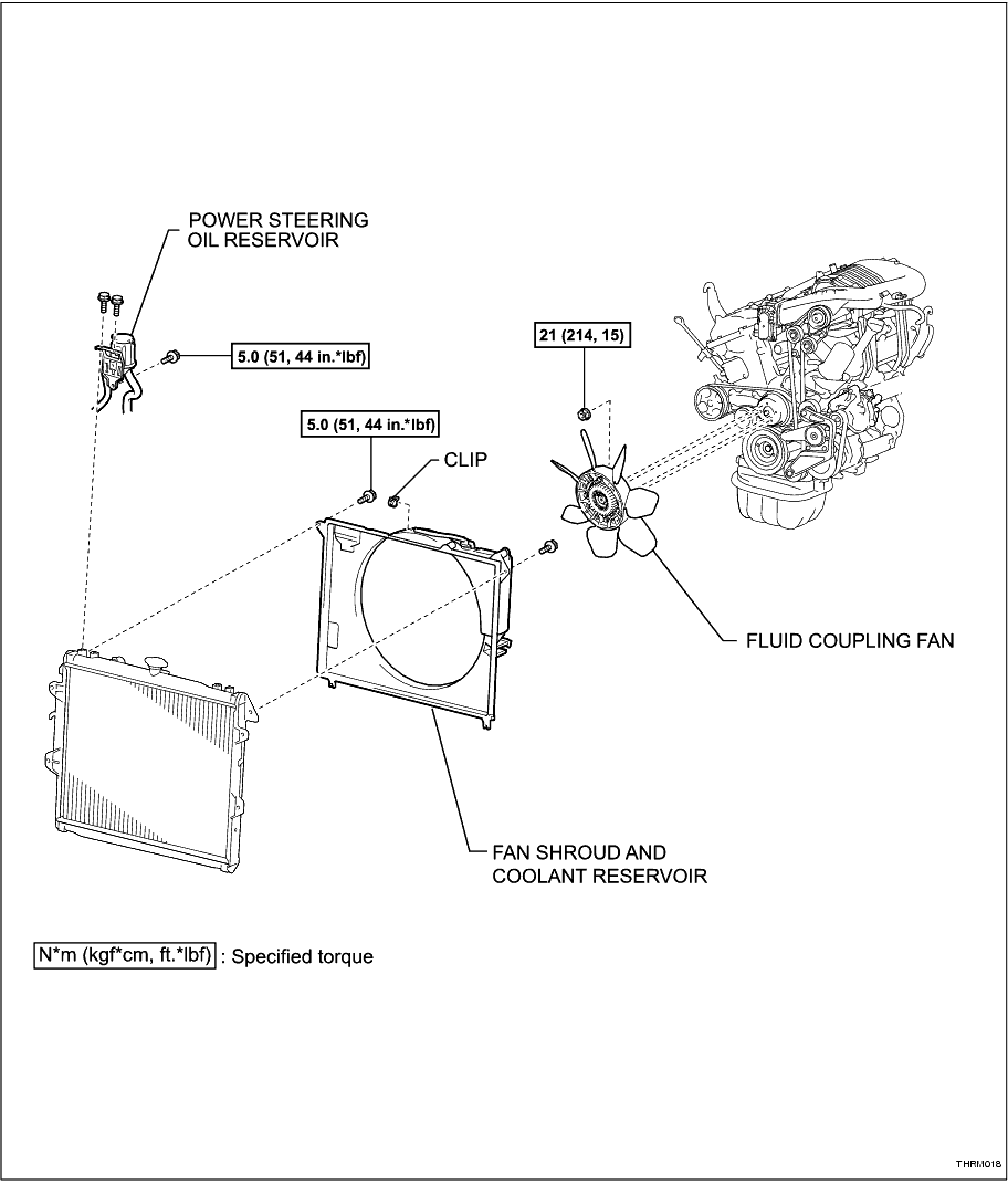
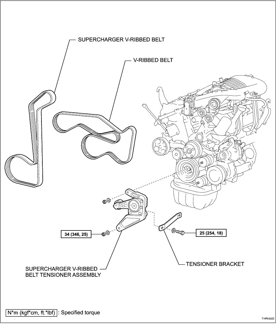
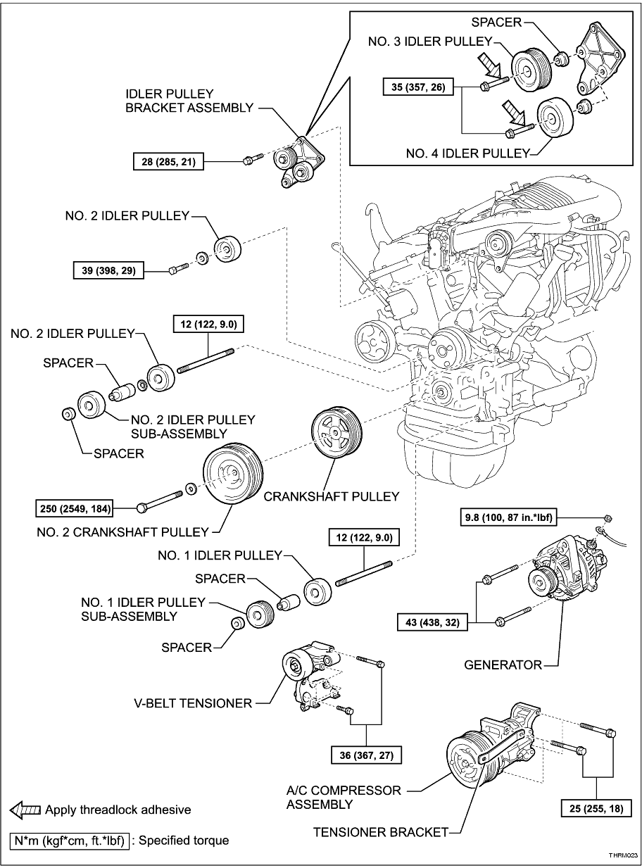
REMOVAL
1. DISCONNECT CABLE FROM NEGATIVE BATTERY TERMINAL
CAUTION:
Wait at least 90 seconds after disconnecting the cable from the negative (-) battery terminal to prevent airbag and seatbelt pretensioner activation.
HINT:
Obtain the audio system PIN from the vehicle owner, if applicable. Otherwise the audio system will be inoperable when the battery cable is reconnected.
2. REMOVE RADIATOR FAN AND SHROUD (
Click Here
)
3. REMOVE SUPERCHARGER V-RIBBED BELT (
Click Here
)
4. REMOVE IDLER PULLEY BRACKET ASSEMBLY
(a) Remove the 3 bolts and idler pulley bracket assembly.
-
(b) Remove the bolt and the No. 3 idler pulley (ribbed) and spacer.
-
(c) Remove the bolt and the No. 4 idler pulley (flat) and spacer.
-
5. REMOVE V-RIBBED BELT (
Click Here
)
6. REMOVE NO. 1 IDLER PULLEY ASSEMBLY
(a) Remove the temporarily fitted nut.
-
(b) Remove the spacer, No. 1 idler pulley sub-assembly, small stepped spacer and No. 1 idler pulley.
-
(c) Remove the idler pulley mounting stud.
-
7. REMOVE NO. 2 IDLER PULLEY ASSEMBLY
(a) Remove the temporarily fitted nut.
-
(b) Remove the spacer, No. 2 idler pulley sub-assembly, large stepped spacer, washer and No. 2 idler pulley.
-
(c) Remove the idler pulley mounting stud.
-
8. REMOVE NO. 2 IDLER PULLEY
(a) Remove the bolt, spacer and No. 2 idler pulley.
-
9. REMOVE GENERATOR ASSEMBLY
(a) Remove the nut and generator wire.
-
(b) Disconnect the generator connector.
-
(c) Remove the 2 bolts and generator.
-
10. REMOVE A/C COMPRESSOR ASSEMBLY
HINT:
Do not disconnect the air conditioner pipes. Move the compressor to one side and secure it to the vehicle.
(a) Remove the 4 bolts and tensioner bracket and the A/C compressor assembly.
-
11. REMOVE V-RIBBED BELT TENSIONER
(a) Remove the 5 bolts and V-ribbed belt tensioner.
-
12. REMOVE NO. 2 CRANKSHAFT PULLEY AND CRANKSHAFT PULLEY
(a) Using SST, hold the crankshaft pulleys and loosen the pulley set bolt.
SST
09213-54015
(91651-60855)
09330-00021
-
(b) Remove the SST and the pulley set bolt and washer.
-
(c) Remove the No. 2 crankshaft pulley.
-
(d) Using SST, remove the crankshaft pulley.
SST
09950-50013
(09951-05010
09952-05010
09953-05020
09954-05030)
-
INSTALLATION
1. INSTALL NO. 2 CRANKSHAFT PULLEY AND CRANKSHAFT PULLEY
(a) Using SST and the pulley set bolt, install the crankshaft pulley by tightening the set bolt firmly.
SST
09213-54015
(91651-60855)
09330-00021
-
(b) Remove the set bolt.
-
(c) Fit the No. 2 crankshaft pulley ensuring the dowel pin is correctly aligned.
-
(d) Install the pulley set bolt and washer.
-
(e) Using SST, tighten the pulley set bolt.
SST
09213-54015
(91651-60855)
09330-00021
Torque:
250 N*m
(2,549 kgf*cm,
184 ft.*lbf)
-
2. INSTALL V-RIBBED BELT TENSIONER
(a) Temporarily install the V-ribbed belt tensioner with the 5 bolts.
-
(b) Install the V-ribbed belt tensioner by tightening bolt 1 and then bolt 2.
Torque:
36 N*m
(367 kgf*cm,
27 ft.*lbf)
-
(c) Tighten the other bolts.
Torque:
36 N*m
(367 kgf*cm,
27 ft.*lbf)
HINT:
Each bolt length is as follows:
A = 70 mm (2.76 in.)
B = 33 mm (1.30 in.)
-
3. INSTALL A/C COMPRESSOR ASSEMBLY
(a) Install the A/C compressor assembly and tensioner bracket with the 4 bolts. Do not tighten.
-
(b) Tighten the bolts in the sequence shown.
Torque:
25 N*m
(255 kgf*cm,
18 ft.*lbf)
-
4. INSTALL GENERATOR ASSEMBLY
(a) Install the generator with the 2 bolts.
Torque:
43 N*m
(438 kgf*cm,
32 ft.*lbf)
-
(b) Install the generator wire with the nut.
Torque:
9.8 N*m
(100 kgf*cm,
87 in.*lbf)
-
(c) Connect the generator connector.
-
5. INSTALL NO. 2 IDLER PULLEY
(a) Install the No. 2 idler pulley and spacer with the bolt.
Torque:
39 N*m
(398 kgf*cm,
29 ft.*lbf)
-
6. INSTALL NO. 2 IDLER PULLEY ASSEMBLY
(a) Install the idler pulley mounting stud.
Torque:
12 N*m
(122 kgf*cm,
9.0 ft.*lbf)
-
(b) Install the No. 2 idler pulley, washer, large stepped spacer, No. 2 idler pulley sub-assembly and spacer.
-
(c) Temporarily fit the nut.
-
7. INSTALL NO. 1 IDLER PULLEY ASSEMBLY
(a) Install the idler pulley mounting stud.
Torque:
12 N*m
(122 kgf*cm,
9.0 ft.*lbf)
-
(b) Install the No. 1 idler pulley, small stepped spacer, No.1 idler pulley sub-assembly and spacer.
HINT:
DOUBLE is marked on the No. 1 idler pulley to distinguish it from the No. 2 idler pulley.
-
(c) Temporarily fit the nut.
-
8. INSTALL V-RIBBED BELT (
Click Here
)
9. INSTALL IDLER PULLEY BRACKET ASSEMBLY
(a) Apply threadlock adhesive to the No. 4 idler pulley bolt.
Adhesive:
Loctite #243 or equivalent
-
(b) Install the No. 4 idler pulley (flat) and spacer with the bolt.
Torque:
35 N*m
(357 kgf*cm,
26 ft.*lbf)
-
(c) Apply threadlock adhesive to the No. 3 idler pulley bolt.
Adhesive:
Loctite #243 or equivalent
-
(d) Install the No. 3 idler pulley (ribbed) and spacer with the bolt.
Torque:
35 N*m
(357 kgf*cm,
26 ft.*lbf)
-
(e) Install the idler pulley bracket assembly with the 3 bolts.
Torque:
28 N*m
(285 kgf*cm,
21 ft.*lbf)
-
10. INSTALL SUPERCHARGER V-RIBBED BELT (
Click Here
)
11. INSTALL RADIATOR FAN AND SHROUD (
Click Here
)
12. CONNECT CABLE TO NEGATIVE BATTERY TERMINAL
13. PERFORM INITIALISATION
(a) Enter the audio system PIN, if applicable. Refer to Section 1-8 "Audio System" in the TRD Hilux Driver's Manual for programming information.
-
(b) Calibrate the multi-information display compass. Refer to Section 1-10 "Other Equipment" in the TRD Hilux Driver's Manual for calibrating information.
-