Intercooler System
Intercooler
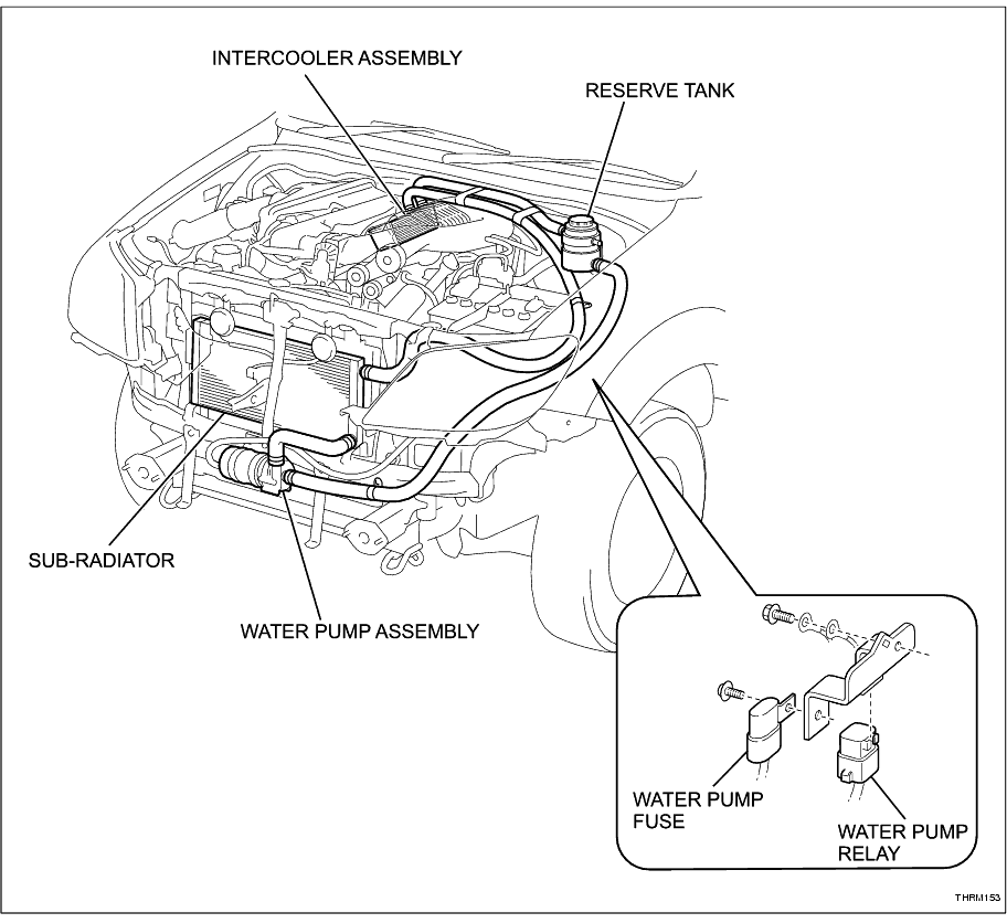
PARTS LOCATION
SYSTEM DESCRIPTION
1. SUPERCHARGER INTERCOOLER SYSTEM
(a) Cooling the compressed (supercharged) air before it enters the engine increases its density and provides an increase in efficiency.
The intercooler system is responsible for this cooling process.
The intercooler is similar to a small radiator, with coolant passing through a system of tubes. As the hot air exiting the supercharger encounters the cooler tubes, it also cools down.
The reduction in temperature increases the density of the air, which makes a denser charge entering the combustion chamber.
-
(b) The intercooler system consists of the intercooler assembly fitted within the supercharger housing, a reserve coolant tank, a sub-radiator to cool the coolant and an electric pump.
A 20 amp fuse and a relay control the pump, which operates constantly when the engine is running.
-
ON-VEHICLE INSPECTION
1. CHECK COOLANT QUALITY
CAUTION:
Do not remove the reserve tank cap while the system is hot. Pressurised, hot coolant and steam may be released and cause serious burns.
(a) Remove reserve tank cap.
-
(b) Check if there are excessive deposits of rust or scale around the cap and reserve tank opening. Also, the coolant should be free of oil.
If excessively dirty, replace the coolant.
-
(c) Install the reserve tank cap.
-
2. CHECK COOLANT LEVEL
CAUTION:
Do not remove the reserve tank cap while the system is hot. Pressurised, hot coolant and steam may be released and cause serious burns.
(a) Remove reserve tank cap.
-
(b) The coolant should be between the Low and Full lines when the engine is cold as shown.
If low, check for leaks and add Toyota Super Long Life Coolant (SLLC) or similar high quality ethylene glycol based non-silicate, non-amine, non-nitrite, non-borate coolant with long-life hybrid organic acid technology up to the F line.
NOTICE:
Never use water as a substitute for coolant.
-
(c) Install the reserve tank cap.
-
3. CHECK COOLING SYSTEM FOR LEAKS
CAUTION:
Do not remove the reserve tank cap while the system is hot. Pressurised, hot coolant and steam may be released and cause serious burns.
(a) Fill the system with coolant.
-
(b) Connect a radiator pressure tester to the SST.
SST
J-49364
-
(c) Attach the SST to the reserve tank.
-
(d) Warm up the system.
-
(e) Using the pressure tester, increase the pressure inside the reserve tank to 69 kPa (10 psi), and check the pressure does not drop.
If the pressure drops, check the hoses, sub-radiator and water pump for leaks. If no external leaks are found, remove the supercharger cover and inspect the intercooler (
Click Here
)
-
(f) Remove the SST from the reserve tank.
-
(g) Fit the SST F-F adapter to the SST.
SST
J-49367
-
(h) Attach the reserve tank cap to the adaptor.
-
(i) Using the pressure tester, increase the pressure to 69 kPa (10 psi), and check the pressure does not drop.
If the pressure drops, replace the cap.
-
DIAGNOSIS
HINT:
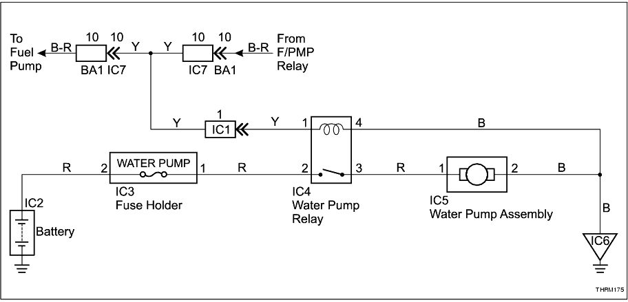
The intercooler cooling system water pump circuit is integrated within the fuel pump control circuit and will only operate when the fuel pump is operating. The ECM controls the fuel pump circuit and operates the pump when a rpm signal is received from the engine.
Therefore, ensure the fuel pump circuit is operating correctly before diagnosing problems with the intercooler water pump circuit.
WATER PUMP DOES NOT OPERATE
DESCRIPTION
INSPECTION PROCEDURE
-
1
.
INSPECT FUSE (WATER PUMP)
-
NG
REPLACE THE FUSE
-
OK
-
-
2
.
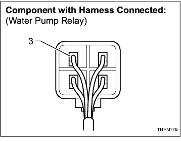
CHECK WATER PUMP RELAY (OPERATION)
-
OK
GO TO STEP 6
-
NG
-
-
3
.
CHECK WIRE HARNESS AND CONNECTOR (WATER PUMP RELAY IGNITION VOLTAGE)
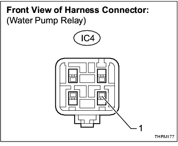
(a) Disconnect water pump relay connector IC4 and check for voltage.
Standard:
|
IC4-1 - Body ground
|
Ignition switch ON
|
11 to 14 V
|
-
NG
REPAIR OR REPLACE HARNESS OR CONNECTOR OR INSPECT FUEL PUMP CIRCUIT (
not in this collection
)
-
OK
-
-
4
.
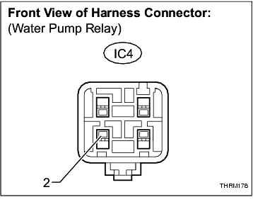
CHECK WIRE HARNESS AND CONNECTOR (WATER PUMP RELAY BATTERY VOLTAGE)
-
NG
REPAIR OR REPLACE HARNESS OR CONNECTOR
-
OK
-
-
5
.
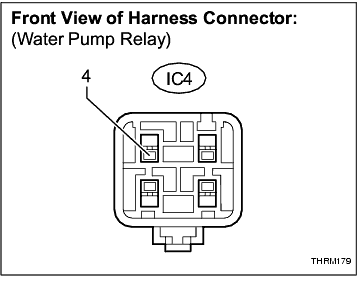
CHECK WIRE HARNESS AND CONNECTOR (WATER PUMP RELAY GROUND)
-
NG
REPAIR OR REPLACE HARNESS OR CONNECTOR
-
OK
-
-
6
.
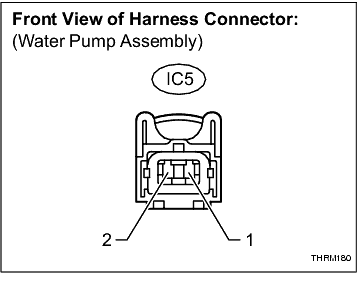
CHECK WIRE HARNESS AND CONNECTOR (WATER PUMP ASSEMBLY)