Front Bumper
Exterior · Vehicles built Up to Oct 2008
Versions by build date: Up to Oct 2008 From Oct 2008
COMPONENTS
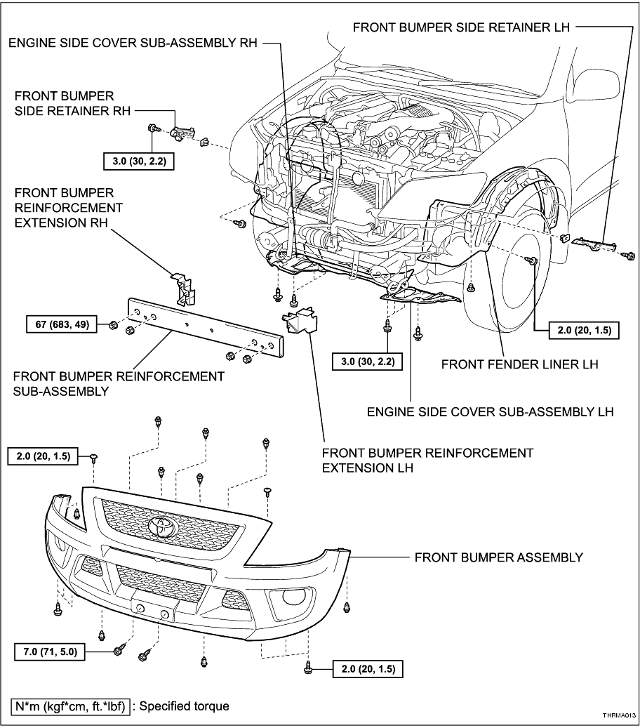
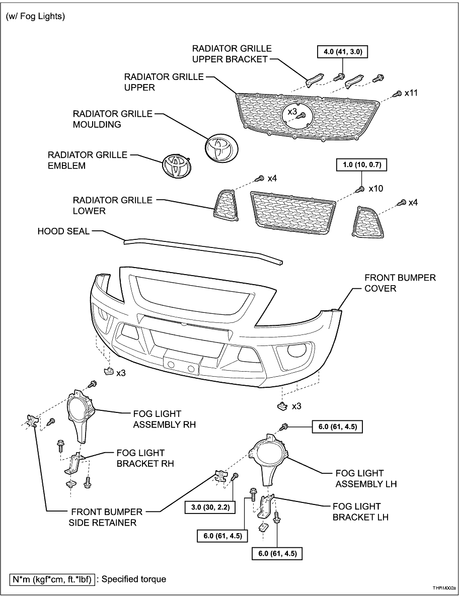
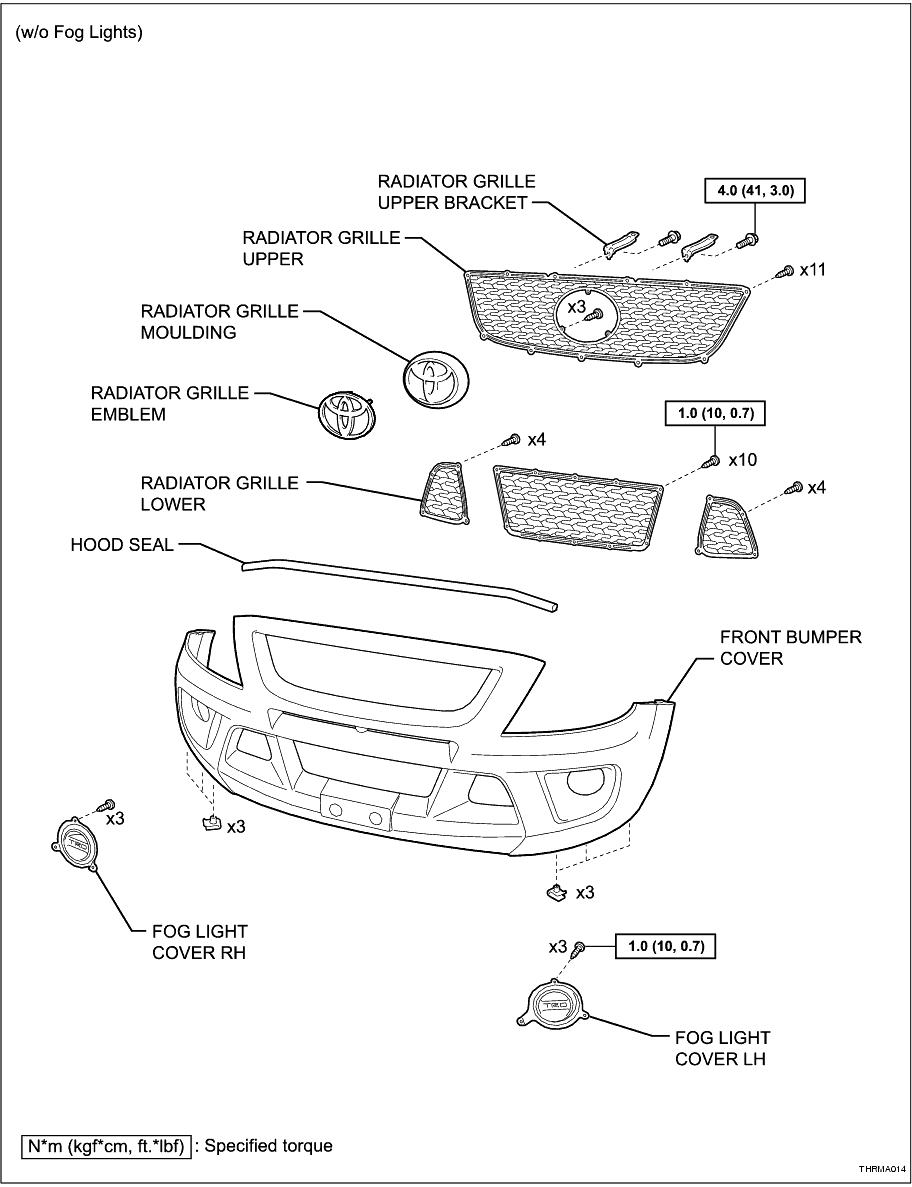
REMOVAL
1. DISCONNECT CABLE FROM NEGATIVE BATTERY TERMINAL (w/ Fog Lights)
CAUTION:
Wait at least 90 seconds after disconnecting the cable from the negative (-) battery terminal to prevent airbag and seatbelt pretensioner activation.
HINT:
Obtain the audio system PIN from the vehicle owner, if applicable. Otherwise the audio system will be inoperable when the battery cable is reconnected.
2. REMOVE FRONT FENDER LINER LH
(a) Remove the screw.
-
(b) Using a clip remover, remove the 3 clips.
-
(c) Partially remove the fender liner.
HINT:
It is not necessary to fully remove the fender liner. Partially remove it so that the front bumper cover can be removed in a later step.
-
3. REMOVE FRONT FENDER LINER RH
HINT:
Use the same procedures described for the LH side.
4. REMOVE FRONT BUMPER ASSEMBLY
(a) Using a clip remover, remove the 4 clips.
-
(b) Remove the 2 screws (A).
-
(c) Remove the 6 screws (B).
-
(d) Using a clip remover, remove the 5 clips.
HINT:
Remove the foam washers from under each upper radiator grille bracket.
-
(e) Remove the 2 screws.
-
(f) Put protective tape under the front fender.
-
(g) Detach the 4 claws and remove the bumper assembly.
-
(h) w/ Fog Lights:
Disconnect the 2 fog light connectors.
-
5. REMOVE FRONT BUMPER SIDE RETAINER LH
(a) Remove the screw.
-
(b) Using a screwdriver, detach the 2 claws and remove the side retainer.
HINT:
Tape the screwdriver tip before use.
-
6. REMOVE FRONT BUMPER SIDE RETAINER RH
HINT:
Use the same procedures described for the LH side.
7. REMOVE ENGINE SIDE COVER SUB-ASSEMBLY LH
(a) Using a clip remover, remove the 2 clips.
-
(b) Remove the 2 screws and engine side cover.
-
8. REMOVE ENGINE SIDE COVER SUB-ASSEMBLY RH
HINT:
Use the same procedures described for the LH side.
9. REMOVE FRONT BUMPER REINFORCEMENT SUB-ASSEMBLY
(a) Remove the 4 nuts and reinforcement.
-
10. REMOVE FRONT BUMPER REINFORCEMENT EXTENSION LH
(a) Using a screwdriver, detach the claws and remove the reinforcement extension.
HINT:
Tape the screwdriver tip before use.
-
11. REMOVE FRONT BUMPER REINFORCEMENT EXTENSION RH
HINT:
Use the same procedures described for the LH side.
DISASSEMBLY
1. REMOVE FOG LIGHT ASSEMBLY LH (w/ Fog Lights) (
Click Here
)
2. REMOVE FOG LIGHT ASSEMBLY RH (w/ Fog Lights)
HINT:
Use the same procedures described for the LH side.
3. REMOVE FOG LIGHT MOUNTING BRACKETS LH (w/ Fog Lights)
(a) Remove the screw and the front bumper side retainer (upper bracket).
-
(b) Remove the screw and the fog light bracket.
-
4. REMOVE FOG LIGHT MOUNTING BRACKETS RH (w/ Fog Lights)
HINT:
Use the same procedures described for the LH side.
5. REMOVE FRONT BUMPER HOLE COVER LH (w/o Fog Lights)
(a) Remove the 3 screws and remove the cover.
-
6. REMOVE FRONT BUMPER HOLE COVER RH (w/o Fog Lights)
HINT:
Use the same procedures described for the LH side.
7. REMOVE UPPER RADIATOR GRILLE
(a) Remove the 11 screws and remove the radiator grille.
-
(b) Remove the 3 screws and remove the radiator grille moulding.
-
(c) Detach the 2 side retainers (1) and remove the radiator grille emblem while disengaging the lower retainer (2).
-
8. REMOVE LOWER RADIATOR GRILLE LH
(a) Remove the 4 screws and remove the lower radiator grille LH.
-
9. REMOVE LOWER RADIATOR GRILLE RH
HINT:
Use the same procedures described for the LH side.
10. REMOVE LOWER RADIATOR GRILLE
(a) Remove the 10 screws and remove the lower radiator grille.
-
11. REMOVE RADIATOR UPPER SEAL
HINT:
When removing the radiator upper seal, heat the seal and bumper cover using a heat light.
(a) Carefully prise the radiator upper seal from the bumper cover.
-
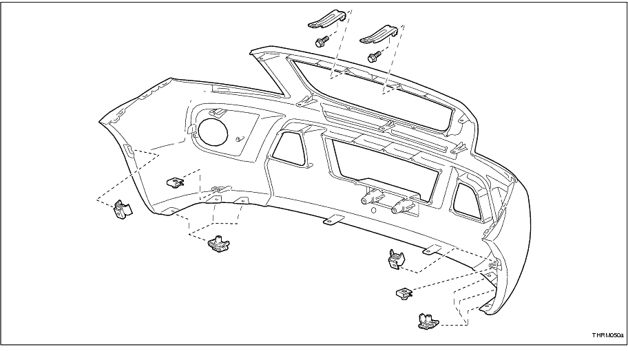
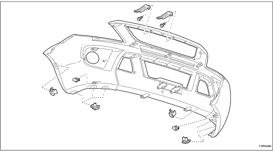
12. REMOVE FRONT BUMPER RETAINERS
(a) Remove the screw and remove the LH upper radiator grille bracket.
-
(b) Remove the screw and remove the RH upper radiator grille bracket.
-
(c) Using a screwdriver, remove the 8 fender liner retainers and 2 fog light retainers, if fitted.
-
REASSEMBLY
1. INSTALL FRONT BUMPER RETAINERS
(a) Install the 8 fender liner retainers and 2 fog light retainers, if fitted.
-
(b) Install the RH upper radiator grille bracket with the screw.
Torque:
4.0 N*m
(41 kgf*cm,
3.0 ft.*lbf)
-
(c) Install the LH upper radiator grille bracket with the screw.
Torque:
4.0 N*m
(41 kgf*cm,
3.0 ft.*lbf)
-
2. INSTALL RADIATOR UPPER SEAL
HINT:
• Ensure the bumper cover surface is clean and dry.
• Ensure the seal is correctly orientated.
• When installing the radiator upper seal, heat the seal and bumper cover using a heat light.
(a) Partially remove the backing paper and affix one end of the radiator upper seal to the bumper cover.
-
(b) Continue removing the backing paper while affixing the seal to the bumper cover.
-
3. INSTALL LOWER RADIATOR GRILLE
(a) Install the lower radiator grille with the 10 screws.
Torque:
1.0 N*m
(10 kgf*cm,
0.7 ft.*lbf)
-
4. INSTALL LOWER RADIATOR GRILLE LH
(a) Install the lower radiator grille LH with the 4 screws.
Torque:
1.0 N*m
(10 kgf*cm,
0.7 ft.*lbf)
-
5. INSTALL LOWER RADIATOR GRILLE RH
HINT:
Use the same procedures described for the LH side.
6. INSTALL UPPER RADIATOR GRILLE
(a) Install the radiator grille emblem by engaging the lower retainer (2) and attaching the 2 side retainers (1).
-
(b) Install the radiator grille moulding with the 3 screws.
Torque:
1.0 N*m
(10 kgf*cm,
0.7 ft.*lbf)
-
(c) Install the radiator grille with the 11 screws.
Torque:
1.0 N*m
(10 kgf*cm,
0.7 ft.*lbf)
-
7. INSTALL FRONT BUMPER HOLE COVER LH (w/o Fog Lights)
(a) Install the cover with the 3 screws.
Torque:
1.0 N*m
(10 kgf*cm,
0.7 ft.*lbf)
-
8. INSTALL FRONT BUMPER HOLE COVER RH (w/o Fog Lights)
HINT:
Use the same procedures described for the LH side.
9. INSTALL FOG LIGHT MOUNTING BRACKETS LH (w/ Fog Lights)
(a) Install the front bumper side retainer (upper bracket) with the screw.
Torque:
3.0 N*m
(30 kgf*cm,
2.2 ft.*lbf)
-
(b) Install the fog light bracket with the screw.
Torque:
6.0 N*m
(61 kgf*cm,
4.5 ft.*lbf)
-
10. INSTALL FOG LIGHT MOUNTING BRACKETS RH (w/ Fog Lights)
HINT:
Use the same procedures described for the LH side.
11. INSTALL FOG LIGHT ASSEMBLY LH (w/ Fog Lights) (
Click Here
)
12. INSTALL FOG LIGHT ASSEMBLY RH (w/ Fog Lights)
HINT:
Use the same procedures described for the LH side.
INSTALLATION
1. INSTALL FRONT BUMPER REINFORCEMENT EXTENSION LH
(a) Install the reinforcement extension and attach the claws.
-
2. INSTALL FRONT BUMPER REINFORCEMENT EXTENSION RH
HINT:
Use the same procedures described for the LH side.
3. INSTALL FRONT BUMPER REINFORCEMENT SUB-ASSEMBLY
(a) Install the reinforcement with the 4 nuts.
Torque:
67 N*m
(683 kgf*cm,
49 ft.*lbf)
-
4. INSTALL ENGINE SIDE COVER SUB-ASSEMBLY LH
(a) Install the engine side cover with the 2 screws.
Torque:
3.0 N*m
(30 kgf*cm,
2.2 ft.*lbf)
-
(b) Install the 2 clips.
-
5. INSTALL ENGINE SIDE COVER SUB-ASSEMBLY RH
HINT:
Use the same procedures described for the LH side.
6. INSTALL FRONT BUMPER SIDE RETAINER LH
(a) Install the side retainer, attaching the 2 claws.
-
(b) Install the screw.
Torque:
3.0 N*m
(30 kgf*cm,
2.2 ft.*lbf)
-
7. INSTALL FRONT BUMPER SIDE RETAINER RH
HINT:
Use the same procedures described for the LH side.
8. INSTALL FRONT BUMPER ASSEMBLY
(a) w/ Fog Lights:
Connect the 2 fog light connectors.
-
(b) Install the bumper assembly and attach the 4 claws.
-
(c) Install the 2 screws.
Torque:
2.0 N*m
(20 kgf*cm,
1.5 ft.*lbf)
-
(d) Install the 5 clips.
HINT:
Install a foam washer under each upper radiator grille bracket.
-
(e) Install the 2 screws (A).
Torque:
7.0 N*m
(71 kgf*cm,
5.0 ft.*lbf)
-
(f) Install the 6 screws (B).
Torque:
2.0 N*m
(20 kgf*cm,
1.5 ft.*lbf)
-
(g) Install the 4 clips.
-
9. INSTALL FRONT FENDER LINER LH
(a) Install the partially removed fender liner.
-
(b) Install the screw.
Torque:
2.0 N*m
(20 kgf*cm,
1.5 ft.*lbf)
-
(c) Install the 3 clips.
-
10. INSTALL FRONT FENDER LINER RH
HINT:
Use the same procedures described for the LH side.
11. CONNECT CABLE TO NEGATIVE BATTERY TERMINAL
12. ADJUST FOG LIGHT AIMING (w/ Fog Lights) (
Click Here
)
13. PERFORM INITIALISATION
(a) Enter the audio system PIN, if applicable. Refer to Section 1-8 "Audio System" in the TRD Hilux Driver's Manual for programming information.
-
(b) Calibrate the multi-information display compass. Refer to Section 1-10 "Other Equipment" in the TRD Hilux Driver's Manual for calibrating information.
-