FOG Light Assembly
Lighting · Vehicles built Up to Oct 2008
Versions by build date: Up to Oct 2008 From Oct 2008
COMPONENTS
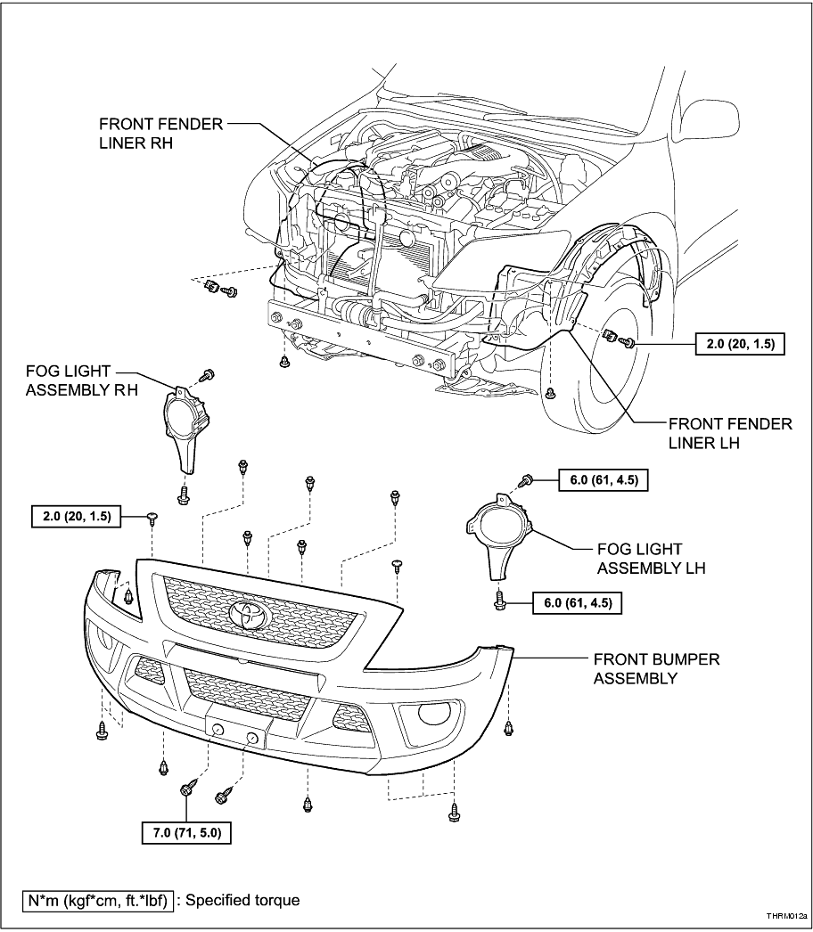
ADJUSTMENT
1. VEHICLE PREPARATION FOR FOG LIGHT AIM ADJUSTMENT
(a) Prepare the vehicle:
• Ensure the vehicle has no damage or deformation around the fog lights.
• Fill the fuel tank.
• Ensure oils in the vehicle (engine oil, etc.) are filled to the specified levels.
• Ensure the coolant is filled to the specified level.
• Inflate the tyres to the correct pressure.
• Fit the spare tyre, tools, and jack in their original positions.
• Unload the passenger compartment and rear body.
• Have a person that weighs approximately 75 kg sit in the driver's seat.
-
2. PREPARATION FOR FOG LIGHT AIMING (Using a screen)
(a) Prepare the vehicle according to the following conditions:
• Move the vehicle to a location that is sufficiently dark so the fog light beam cut-off line can be visually checked. The cut-off line is a distinct plane below which the light is projected.
• Move the vehicle to a level surface.
• Point the front of the vehicle at a wall. The wall must be perpendicular to the surface the vehicle is on.
• Position the vehicle 10 m from the wall.
• Push down on the vehicle several times to settle the suspension.
HINT:
A distance of 10 m between the vehicle and the wall is required for correct aim adjustment. If unavailable, secure a distance of exactly 3 m.
-
(b) Prepare a piece of thick white paper that is approximately 2 m (height) x 4 m (width) to use as a screen.
-
(c) Draw a vertical line down the centre of the screen (V line).
-
(d) Set the screen as shown in the illustration.
HINT:
• Stand the screen perpendicular to the ground.
• Align the V line on the screen with the centre of the vehicle.
-
(e) Draw base lines (H line and V LH, V RH lines) on the screen as shown in the illustration.
HINT:
• Mark the fog light bulb centre marks on the screen. If the centre mark cannot be observed on the fog light, use the centre of the fog light bulb.
(1) H line (fog light height):
Draw a horizontal line across the screen so that it passes through the centre marks. The H line should be at the same height as the fog light bulb centre marks.
(2) V LH line, V RH line (centre mark position of LH and RH fog light):
Draw two vertical lines intersecting the H line at each centre mark.
-
3. FOG LIGHT AIMING INSPECTION
(a) Cover or disconnect the opposite fog light to prevent its light affecting the fog light aiming inspection.
NOTICE:
Do not keep the fog light covered for more than 3 minutes.
-
(b) Start the engine.
-
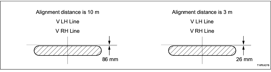
(c) Turn the fog lights on and check the cut-off line is within the specified area shown in the illustration.
-
4. FOG LIGHT AIMING ADJUSTMENT
(a) Adjust the vertical fog light aim into the specified range by turning the aiming screw with a screwdriver.
NOTICE:
The final turn of the aiming screw should be made in the clockwise direction.
-
REMOVAL
1. DISCONNECT CABLE FROM NEGATIVE BATTERY TERMINAL
CAUTION:
Wait at least 90 seconds after disconnecting the cable from the negative (-) battery terminal to prevent airbag and seatbelt pretensioner activation.
HINT:
Obtain the audio system PIN from the vehicle owner, if applicable. Otherwise the audio system will be inoperable when the battery cable is reconnected.
2. REMOVE FRONT FENDER LINER LH (
Click Here
)
3. REMOVE FRONT FENDER LINER RH
HINT:
Use the same procedures described for the LH side.
4. REMOVE FRONT BUMPER ASSEMBLY (
Click Here
)
5. REMOVE FOG LIGHT ASSEMBLY LH
(a) Remove the 2 bolts and fog light assembly.
-
6. REMOVE FOG LIGHT ASSEMBLY RH
HINT:
Use the same procedures described for the LH side.
DISASSEMBLY
1. REMOVE FOG LIGHT BULB LH
(a) Turn the bulb/socket unit in the direction indicated by the arrow and pull to remove it.
-
2. REMOVE FOG LIGHT BULB RH
HINT:
Use the same procedures described for the LH side.
REASSEMBLY
1. INSTALL FOG LIGHT BULB RH
(a) Turn the bulb/socket unit in the direction indicated by the arrow to install it.
-
2. INSTALL FOG LIGHT BULB LH
HINT:
Use the same procedures described for the LH side.
INSTALLATION
1. INSTALL FOG LIGHT ASSEMBLY LH
(a) Install the fog light assembly with the 2 bolts.
Torque:
6.0 N*m
(61 kgf*cm,
4.5 ft.*lbf)
-
2. INSTALL FOG LIGHT ASSEMBLY RH
HINT:
Use the same procedures described for the LH side.
3. INSTALL FRONT BUMPER ASSEMBLY (
Click Here
)
4. INSTALL FRONT FENDER LINER LH (
Click Here
)
5. INSTALL FRONT FENDER LINER RH
HINT:
Use the same procedures described for the LH side.
6. CONNECT CABLE TO NEGATIVE BATTERY TERMINAL
7. ADJUST FOG LIGHT AIMING (
Click Here
)
8. PERFORM INITIALISATION
(a) Enter the audio system PIN, if applicable. Refer to Section 1-8 "Audio System" in the TRD Hilux Driver's Manual for programming information.
-
(b) Calibrate the multi-information display compass. Refer to Section 1-10 "Other Equipment" in the TRD Hilux Driver's Manual for calibrating information.
-