OIL PUMP (w/o EGR Cooler) > REMOVAL |
| 1. REMOVE ENGINE ASSEMBLY |
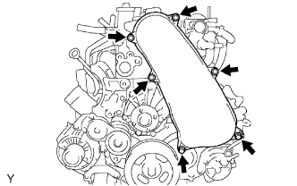
| 2. REMOVE NO. 1 TIMING BELT COVER |
|
Remove the bolt and water hose clamp.
Remove the wire harness clamp.
Remove the 6 bolts and timing belt cover.
| 3. REMOVE TIMING BELT |
| 4. REMOVE NO. 1 TIMING BELT TENSIONER ASSEMBLY |
| 5. REMOVE NO. 2 IDLE PULLEY ASSEMBLY |
| 6. REMOVE GENERATOR ASSEMBLY |
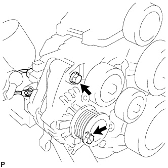 |
Remove the nut and generator wire.
Disconnect the generator connector.
Remove the 2 bolts and generator.
| 7. REMOVE GENERATOR BRACKET |
Remove the bolt and generator bracket.
| 8. REMOVE V-RIBBED BELT TENSIONER ASSEMBLY |
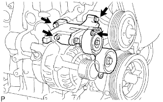 |
Remove the 4 bolts and V-ribbed belt tensioner.
| 9. REMOVE NO. 1 COMPRESSOR MOUNTING BRACKET |
Remove the 4 bolts and No. 1 compressor mounting bracket.
| 10. REMOVE MANIFOLD STAY |
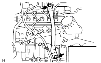 |
Remove the 2 bolts and stay.
| 11. REMOVE FUEL INLET PIPE SUB-ASSEMBLY |
Remove the engine oil level dipstick.
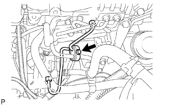 |
Remove the bolt and clamp.
Remove the bolt and engine oil level dipstick guide.
Remove the O-ring engine oil level dipstick guide.
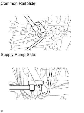 |
Using a 17 mm union nut wrench, loosen the union nuts and remove the fuel inlet pipe.
| 12. REMOVE NO. 1, NO. 2 AND NO. 3 INJECTION PIPE SUB-ASSEMBLY |
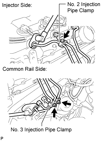 |
Remove the bolt and No. 2 injection pipe clamp.
Remove the 2 nuts and No. 3 injection pipe clamp.
Using a 17 mm union nut wrench, loosen the union nuts and remove the No. 1, No. 2 and No. 3 injection pipes.
| 13. REMOVE NO. 4 INJECTION PIPE SUB-ASSEMBLY |
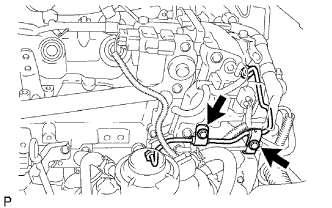 |
Remove the 2 bolts and disconnect the 2 injection pipe clamps.
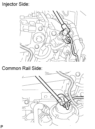 |
Using a 17 mm union nut wrench, loosen the union nuts and remove the No. 4 injection pipe.
| 14. REMOVE CYLINDER HEAD COVER SUB-ASSEMBLY |
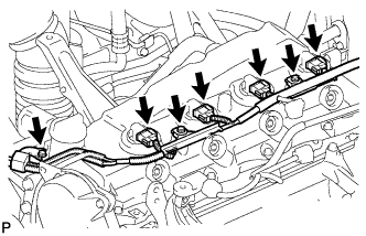 |
Remove the 3 bolts and disconnect the 4 connectors.
Disconnect the ventilation hose.
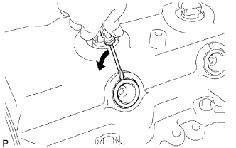 |
Using a small screwdriver, remove the nozzle holder seal by prying the portion between the nozzle holder seal and the cutout part of the cylinder head cover.
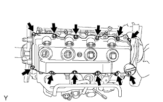 |
Remove the 10 bolts, 2 nuts, cylinder head cover and cylinder head cover gasket.
| 15. REMOVE CAMSHAFT TIMING PULLEY |
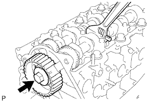 |
Remove the bolt of the camshaft timing pulley by holding the camshaft with a wrench.
Remove the camshaft timing pulley.
| 16. REMOVE NO. 1 TIMING BELT IDLER SUB-ASSEMBLY |
| 17. REMOVE NO. 2 TIMING BELT COVER |
Remove the 4 bolts, nuts and No. 2 timing belt cover.
| 18. REMOVE WATER PUMP ASSEMBLY |
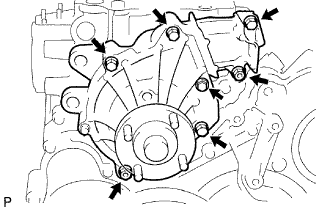 |
Remove the 5 bolts, 2 nuts, water pump and gasket.
| 19. REMOVE VACUUM PUMP ASSEMBLY |
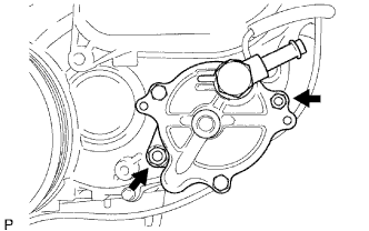 |
Remove the 2 nuts, vacuum pump and 2 O-rings.
| 20. REMOVE VANE PUMP ASSEMBLY |
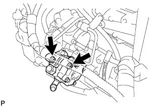 |
Remove the 2 nuts, vane pump and O-ring.
| 21. REMOVE PUMP DRIVE SHAFT PULLEY |
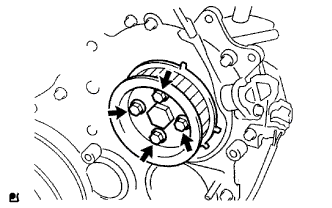 |
Remove the 4 bolts, No. 2 camshaft timing pulley flange and pump drive shaft pulley.
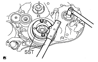 |
Using SST, hold the crankshaft pulley and remove the nut and O-ring.
| 22. REMOVE CRANKSHAFT PULLEY |
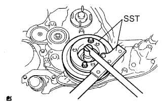 |
Using SST, remove the pulley bolt.
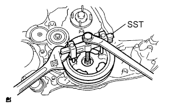 |
Using SST, remove the pulley.
| 23. REMOVE CAMSHAFT POSITION SENSOR |
Remove the bolt and camshaft position sensor.
| 24. REMOVE CRANKSHAFT POSITION SENSOR |
Remove the bolt and crankshaft position sensor.
| 25. REMOVE TIMING GEAR COVER |
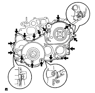 |
Remove the bolt and No. 1 vacuum transmitting pipe.
Remove the 14 bolts and 2 nuts.
Using a slotted screwdriver, gently separate the cover from the timing gear case.
Remove the cover and O-ring.
| 26. FIX NO. 1 IDLE GEAR |
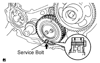 |
Fix the sub idle gear to the idle gear with a service bolt.
| 27. REMOVE CRANKSHAFT TIMING GEAR |
Remove the No. 1 crankshaft sensor plate.
Install a service bolt to the crankshaft.
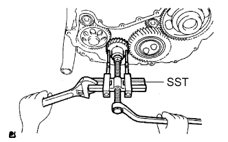 |
Using SST, remove the crankshaft timing gear.
| 28. REMOVE NO. 1 IDLE GEAR |
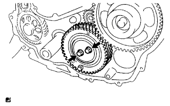 |
Remove the 2 bolts and idle gear thrust plate, and then remove the idle gear together with the sub idle gear.
Remove the No. 1 idle gear shaft.
| 29. REMOVE INJECTION GEAR |
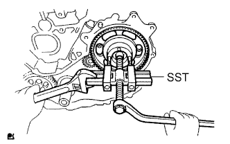 |
Using SST, remove the injection gear.
| 30. REMOVE FUEL SUPPLY PUMP ASSEMBLY |
|
Remove the bolt and clamp.
Remove the 2 bolts and oil level gauge guide.
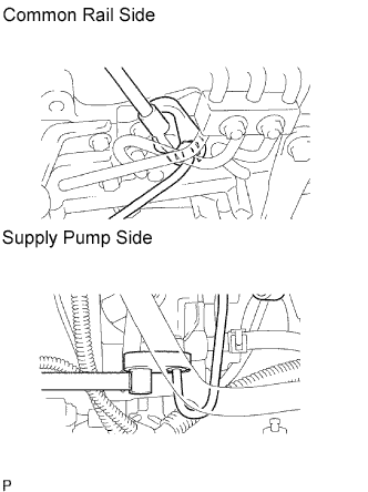 |
Using a 17 mm union nut wrench, loosen the union nuts and remove the fuel inlet pipe.
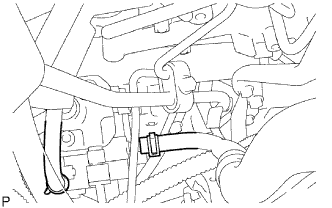 |
Disconnect the 2 fuel hoses.
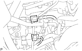 |
Disconnect the 2 connectors.
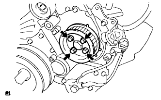 |
Remove the 4 bolts indicated by the arrows in the illustration.
Remove the No. 2 camshaft timing pulley flange and pump drive shaft pulley.
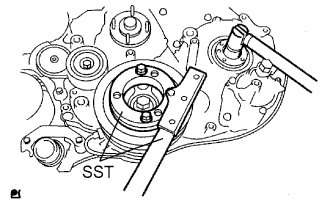 |
Remove the set nut and O-ring while holding the crankshaft pulley by using SST.
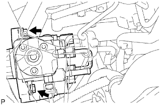 |
Loosen the 2 nuts.
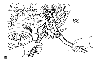 |
Using SST, disconnect the pump from the injection gear.
Remove the 2 nuts and pump.
Remove the O-ring.
| 31. REMOVE OIL PAN SUB-ASSEMBLY |
Remove the 22 bolts and 2 nuts.
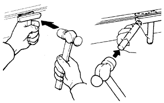 |
Insert the blade of an oil pan seal cutter between the cylinder block and oil pan. Cut through the applied sealer and remove the oil pan.
| 32. REMOVE OIL STRAINER SUB-ASSEMBLY |
Remove the 2 bolts, nut, oil strainer and gasket.
| 33. REMOVE TIMING GEAR CASE ASSEMBLY |
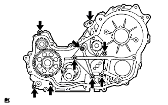 |
Remove the 8 bolts and union bolt. Then remove the timing gear case, 2 O-rings and gasket.