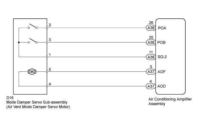
DTC 43 Air Outlet Damper Control Servo Motor Circuit |
| DTC Code | Detection Item | Trouble Area |
| 43 | Air outlet damper control servo motor activation request signal is output, but servo motor position data does not change or is inaccurate |
|
| 1.PERFORM ACTUATOR CHECK |
Warm up the engine.
Enter actuator check mode (Click here).
Press the DEF switch to change to the step operation (Click here).
Press the DEF switch to check the air flow by hand.
| Display Code | Air Flow Vent Position |
| 0 | FACE |
| 1 | FACE |
| 2 | FACE |
| 3 | FACE |
| 4 | FACE |
| 5 | BI-LEVEL |
| 6 | FOOT |
| 7 | FOOT |
| 8 | FOOT/DEF |
| 9 | DEF |
| Result | Proceed to |
| OK (Checking from the PROBLEM SYMPTOMS TABLE) | A |
| OK (Checking from the DTC) | B |
| NG | C |
|
| ||||
|
| ||||
| A | ||
 | ||
| ||
| 2.CHECK HARNESS AND CONNECTOR (MODE DAMPER SERVO - AIR CONDITIONING AMPLIFIER) |
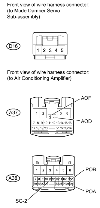 |
Disconnect the D16 servo connector.
Disconnect the A38 and A37 amplifier connectors.
Measure the resistance according to the value(s) in the table below.
| Tester Connection | Condition | Specified Condition |
| D16-4 - A37-4 (AOD) | Always | Below 1 Ω |
| D16-5 - A37-3 (AOF) | ||
| D16-2 - A38-26 (POA) | ||
| D16-3 - A38-25 (POB) | ||
| D16-1 - A38-11 (SG-2) | ||
| D16-4 - Body ground | Always | 10 kΩ or higher |
| D16-5 - Body ground | ||
| D16-2 - Body ground | ||
| D16-3 - Body ground | ||
| D16-1 - Body ground |
|
| ||||
| OK | |
 |
| 3.CHECK MODE DAMPER SERVO SUB-ASSEMBLY (AIR VENT MODE DAMPER SERVO MOTOR) |
Check if the malfunction disappears when a normally functioning mode damper servo (air inlet mode damper servo motor) is installed.
|
| ||||
| OK | ||
| ||
| ||

