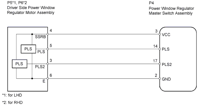
POWER WINDOW CONTROL SYSTEM > Auto Up / Down Function does not Operate |
| 1.CHECK MANUAL UP / DOWN FUNCTION |
Check that the manual UP / DOWN function operates normally.
|
| ||||
| OK | |
 |
| 2.CHECK LIGHT OF MASTER SWITCH |
Turn the ignition switch ON.
Operate the master switch's driver side window switch for 2 seconds or more.
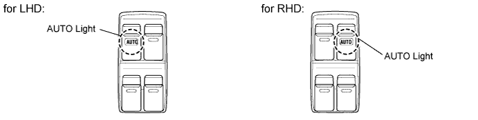
Check the blinking pattern of the AUTO light. Compare the blinking pattern with the illustration.
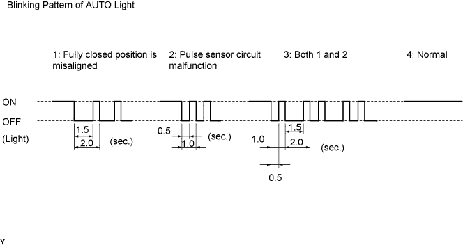
| Blinking Pattern | Proceed to |
| 1 or 3 | A |
| 2 | B |
| 4 | C |
|
| ||||
|
| ||||
| A | |
|
| 3.RESET POWER WINDOW REGULATOR MOTOR ASSEMBLY |
Check that the power window operates normally after reset (Click here).
|
| ||||
| OK | ||
 | ||
| ||
| 4.CHECK WIRE HARNESS (MASTER SWITCH - MOTOR) |
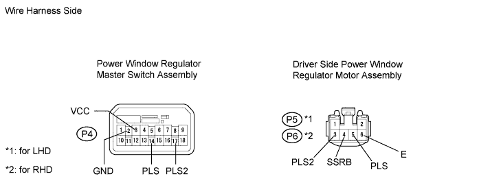
Disconnect the P4 master switch connector.
Disconnect the P5*1 or P6*2 motor connector.
Measure the resistance of the wire harness side connectors.
| Tester Connection | Specified Condition |
| P4-3 (VCC) - P5-4 (SSRB) | Below 1 Ω |
| P4-14 (PLS) - P5-5 (PLS) | Below 1 Ω |
| P4-17 (PLS2) - P5-3 (PLS2) | Below 1 Ω |
| P4-2 (GND) - P5-6 (E) | Below 1 Ω |
| P4-3 (VCC) or P5-4 (SSRB) - Body ground | 10 kΩ or higher |
| P4-14 (PLS) or P5-5 (PLS) - Body ground | 10 kΩ or higher |
| P4-17 (PLS2) or P5-3 (PLS2) - Body ground | 10 kΩ or higher |
| P4-2 (GND) or P5-6 (E) - Body ground | 10 kΩ or higher |
| Tester Connection | Specified Condition |
| P4-3 (VCC) - P6-4 (SSRB) | Below 1 Ω |
| P4-14 (PLS) - P6-5 (PLS) | Below 1 Ω |
| P4-17 (PLS2) - P6-3 (PLS2) | Below 1 Ω |
| P4-2 (GND) - P6-6 (E) | Below 1 Ω |
| P4-3 (VCC) or P6-4 (SSRB) - Body ground | 10 kΩ or higher |
| P4-14 (PLS) or P6-5 (PLS) - Body ground | 10 kΩ or higher |
| P4-17 (PLS2) or P6-3 (PLS2) - Body ground | 10 kΩ or higher |
| P4-2 (GND) - P6-6 (E) - Body ground | 10 kΩ or higher |
|
| ||||
| OK | |
|
| 5.CHECK POWER WINDOW REGULATOR MASTER SWITCH ASSEMBLY (PLS, PLS2 SIGNAL) |
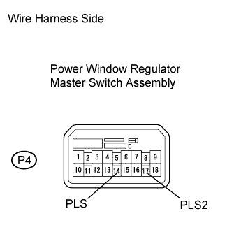 |
Remove the power window regulator master switch assembly with its connectors still connected.
Using an oscilloscope, check the waveform.
| Tester Connection | Condition | Specified Condition |
| P4-14 (PLS) - Body ground | Ignition switch ON, driver side power window switch OFF → UP or DOWN | Pulse waveform is output |
| P4-17 (PLS2) - Body ground |
|
| ||||
| OK | ||
| ||
| ||

