Tighten install the hexagon bolt labeled A using a 5 mm hexagon wrench.
- Torque:
- 13 N*m{ 133 kgf*cm , 10 ft.*lbf }
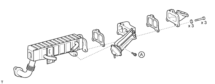
EGR VALVE (w/ EGR Cooler) > INSTALLATION |
| 1. ASSEMBLE EGR VALVE ADAPTER, NO. 2 EGR VALVE ASSEMBLY AND EGR COOLER |
Assemble the EGR valve adapter, No. 2 EGR valve, EGR cooler and 2 gaskets. Then install the 3 plate washers and 3 hexagon bolts using a 6 mm hexagon wrench.
Tighten install the hexagon bolt labeled A using a 5 mm hexagon wrench.
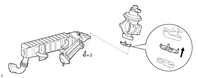
| 2. INSTALL ELECTRIC EGR CONTROL VALVE ASSEMBLY |
Install a new gasket and electric EGR control valve to the EGR valve adapter with the 2 bolts.
| 3. TEMPORARILY INSTALL ELECTRIC EGR CONTROL VALVE WITH NO. 2 EGR VALVE AND EGR COOLER |
Set a new gasket to the cylinder head.
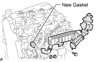 |
Temporarily install the electric EGR control valve with No. 2 EGR valve and EGR cooler with the 2 nuts and bolt.
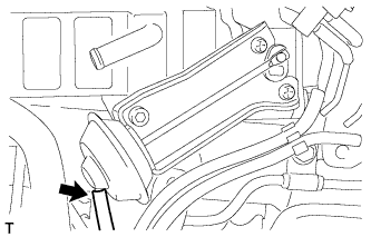 |
Connect the vacuum hose to the No. 2 EGR valve.
| 4. INSTALL NO. 2 INTAKE AIR CONNECTOR |
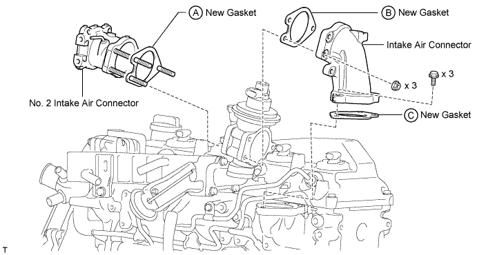
Set a new gasket labeled A to the No. 2 intake air connector as shown in the illustration.
Insert the No. 2 intake air connector with the gasket into the electric EGR control valve.
Install a new gasket labeled B to the electric EGR control valve side shown in the illustration below.
| 5. TEMPORARILY INSTALL INTAKE AIR CONNECTOR |
Set a new gasket labeled C to the intake manifold.
Temporarily install the intake air connector to the intake manifold with the 3 bolts.
Temporarily tighten the intake air connector and electric EGR control valve with the 3 nuts shown in the illustration below.
| 6. TIGHTEN NO. 2 INTAKE AIR CONNECTOR AND INTAKE AIR CONNECTOR |
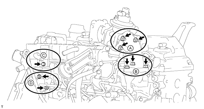
Tighten the 3 nuts shown in the illustration below labeled A.
| 7. TIGHTEN INTAKE AIR CONNECTOR AND INTAKE MANIFOLD |
Tighten the 3 bolts shown in the illustration below labeled B.
| 8. TIGHTEN EGR COOLER |
Tighten the hexagon bolt shown in the illustration below labeled C.
Tighten the 2 nuts shown in the illustration below labeled D.
| 9. INSTALL ELECTRIC VACUUM REGULATING VALVE ASSEMBLY |
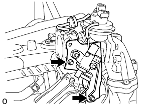 |
Install the E-VRV's bracket with the 2 bolts.
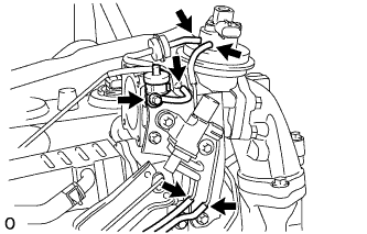 |
Install the gas filter with gas filter bracket with the bolt.
Connect the 5 vacuum hoses see the illustration.
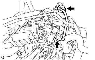 |
Connect the 2 connectors to the electric EGR control valve and E-VRV.
| 10. INSTALL NO. 3 WATER BY-PASS PIPE |
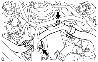 |
Install the No. 3 water by-pass pipe with wire harness with the 2 bolts.
| 11. INSTALL VENTURI BRACKET |
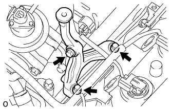 |
Install the venturi bracket with the 3 bolts.
| 12. INSTALL INJECTION PIPE |
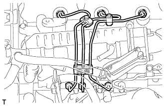 |
Install the No. 1 to 3 injection pipe .
| 13. CONNECT NO. 4 WATER BY-PASS HOSE |
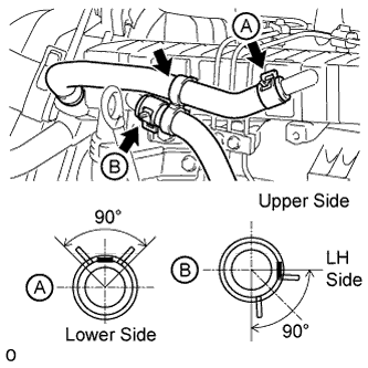 |
Connect the No. 4 water by-pass hose to the EGR cooler.
| 14. CONNECT NO. 3 WATER BY-PASS HOSE |
Connect the No. 3 water by-pass hose to the EGR cooler.
Install the clamp.
| 15. INSTALL DIESEL THROTTLE BODY ASSEMBLY |
Install the diesel throttle body (Click here).
| 16. CONNECT CABLE TO NEGATIVE BATTERY TERMINAL |
| 17. INSPECT FOR FUEL LEAK |
 |
Check that there are no leaks from any part of the fuel system when the engine is stopped.
If there is fuel leakage, repair or replace parts as necessary.
Start the engine and check that there are no leaks from any part of the fuel system.
If there is fuel leakage, repair or replace parts as necessary.
Disconnect the return hose from the common rail.
Start the engine and check for fuel leaks from the return pipe.
If there is fuel leakage, replace the common rail.
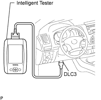
Connect the intelligent tester to the DLC3.
Start the engine and push the intelligent tester main switch ON.
Select the Fuel Leak test from the Active Test mode on the intelligent tester.
If the intelligent tester is not available, fully depress the accelerator pedal quickly. Increase the engine speed to the maximum and maintain that speed for 2 seconds. Repeat this operation several times.
Check that there are no leaks from any part of the fuel system.
Reconnect the return hose to the common rail.
| 18. ADD ENGINE COOLANT |
Tighten the radiator drain cock plug by hand.
Tighten the cylinder block drain cock plug.
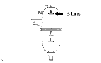 |
Fill the radiator with TOYOTA Super Long Life Coolant (SLLC) to the reservoir tank's B line.
Press the inlet and outlet radiator hoses several times by hand, and then check the level of the coolant.
If the coolant level drops below the B line, add TOYOTA SLLC to the B line.
Install the radiator reservoir cap.
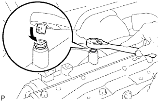 |
Using a wrench, install the vent plug.
Bleed air from the cooling system.
Warm up the engine until the thermostat opens. While the thermostat is open, circulate the coolant for several minutes.
Maintain the engine speed at 2500 to 3000 rpm.
Press the inlet and outlet radiator hoses several times by hand to bleed air.
Stop the engine and wait until the coolant cools down to ambient temperature.
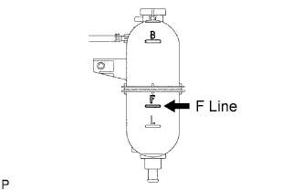 |
After the coolant cools down, check that the coolant level is at the F line.
If the coolant level is below the F line, add TOYOTA SLLC to the F line.
| 19. INSPECT FOR COOLANT LEAK |
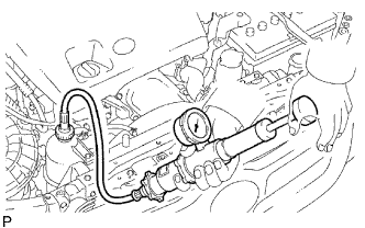 |
Fill the radiator with coolant and attach a radiator cap tester to the radiator reservoir.
Warm up the engine.
Using the radiator cap tester, increase the pressure inside the radiator to 118 kPa (1.2 kgf/cm2 ,17.1 psi), and check that the pressure does not drop.
If the pressure drops, check the hoses, radiator and water pump for leaks.
If no external leaks are found, check the cylinder block and head.
| 20. PERFORM INITIALIZATION |
Perform initialization (Click here).