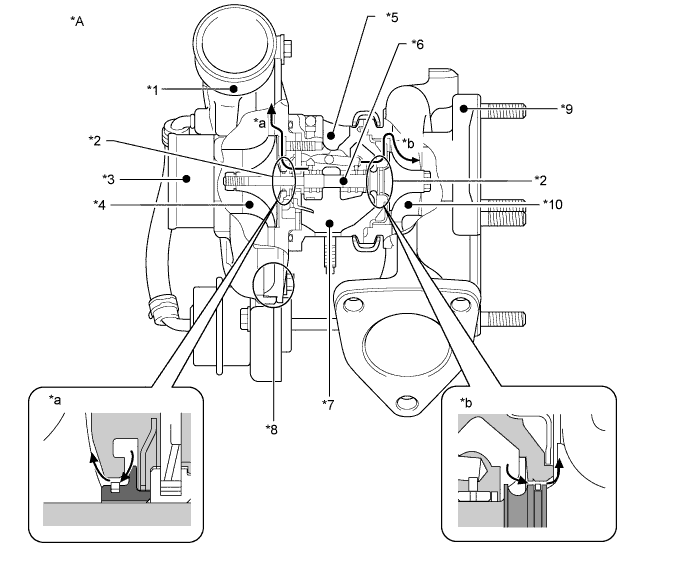
ECD SYSTEM (w/ EGR Cooler) > Turbocharger Oil Leak and White Smoke |
| Oil Leak Type | Description | Main Trouble Area |
| Internal oil leak (White smoke) | Oil leak from bearing housing to compressor housing (intake side) or turbine housing (exhaust side) through seal rings. Internal oil leak is not visible from outside of turbocharger. If oil leak occurs from turbine side seal, large amount of white smoke will be emitted from exhaust pipe. |
|
| External oil leak | Oil leak from inside of turbocharger to outside of turbocharger (e.g. from FIPG seal, oil pipe flange or oil pipe union). Includes oil leak visible from outside of turbocharger. |
|
| *A | Waste Gate Type Turbocharger (vacuum controlled actuator) | - | - |
| *1 | Compressor Housing | *2 | Seal Ring |
| *3 | Compressor Inlet | *4 | Compressor Impeller |
| *5 | Bearing Housing | *6 | Turbine Shaft |
| *7 | Oil Drain (Outlet) | *8 | FIPG Sealing Part |
| *9 | Turbine Housing | *10 | Turbine Wheel |
| *a | Internal Oil Leak to Compressor Housing | *b | Internal Oil Leak to Turbine Housing |
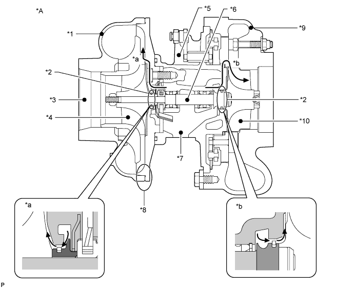
| *A | Variable Nozzle Type Turbocharger (motor controlled actuator) | - | - |
| *1 | Compressor Housing | *2 | Seal Ring |
| *3 | Compressor Inlet | *4 | Compressor Impeller |
| *5 | Bearing Housing | *6 | Turbine Shaft |
| *7 | Oil Drain (Outlet) | *8 | FIPG Sealing Part |
| *9 | Turbine Housing | *10 | Turbine Wheel |
| *a | Internal Oil Leak to Compressor Housing | *b | Internal Oil Leak to Turbine Housing |
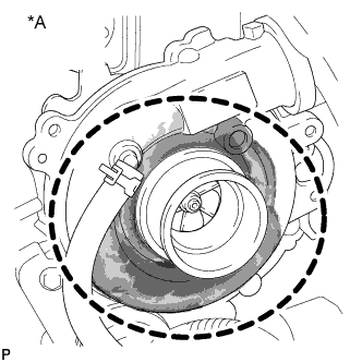
| *A | Fig. 1 | - | - |
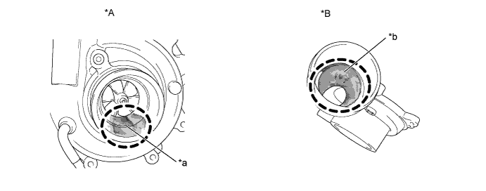
| *A | Fig. 2 | *B | Fig. 3 |
| *a | Oil Existence at Compressor Inlet (Max. 5 cm3) | *b | Oil Existence at Compressor Outlet |
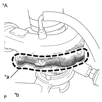
| *A | Fig. 4 | - | - |
| *a | In the case of an actual oil leak, oil leaks from the sealed part | *b | Oil Leak Check Point (FIPG Sealing Part) |
| Faults and Symptoms of Turbocharger Parts |
| Main fault | Seal ring breakage | |
| Symptoms |
| |
| Note |
| |
| Main fault | Seal ring breakage | |
| Symptoms |
| |
| Note |
| |
| Main fault | Oil drain clogging by coked oil | |
| Symptoms | Large amount of white smoke from exhaust pipe | |
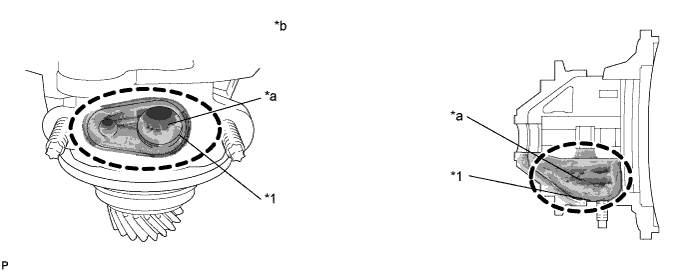
| *1 | Oil Drain | - | - |
| *a | Coked Oil | *b | Oil Drain Clogged with Coked Oil |
| Main fault |
| |
| Symptoms |
| |
| Note |
| |
| Main fault | Breakage | |
| Symptoms |
| |
| Note |
| |
| Symptoms | Oil leak from FIPG sealing part | |
| Note |
| |
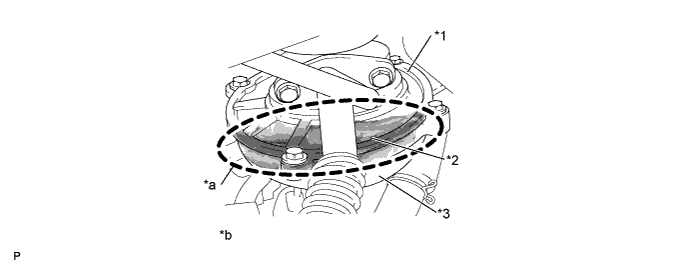
| *1 | Compressor Back Plate | *2 | FIPG Sealing Part |
| *3 | Compressor Housing | - | - |
| *a | Oil Leak | *b | Oil Leak from FIPG Sealing Part |
| Symptoms | Oil leak from hose connection between hose and compressor housing | |
| Note | If oil stain is traced to hose connection part, it can be determined to be due to hose connection failure. | |
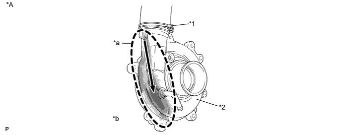
| *A | Fig. 5 | - | - |
| *1 | Compressor Outlet | *2 | Compressor Housing |
| *a | Trace of Oil Leak from Hose Connection Part | *b | Oil Leak from Hose Connection Part |
| 1.CHECK TYPE OF OIL LEAK |
Check whether the oil leak is an internal or external oil leak.
| Oil Leak Type | Description |
| Internal oil leak (White smoke) | Oil leak from bearing housing to compressor housing (intake side) or turbine housing (exhaust side) through seal rings. Internal oil leak is not visible from outside of turbocharger. If oil leak occurs from turbine side seal, large amount of white smoke will be emitted from exhaust pipe. |
| External oil leak | Oil leak from inside of turbocharger to outside of turbocharger (e.g. from FIPG seal, oil pipe flange or oil pipe union). Includes oil leaks visible from outside of turbocharger. |
| Result | Proceed to |
| External oil leak | A |
| Internal oil leak | B |
|
| ||||
| A | |
 |
| 2.REPLACE THE PART WHICH IS LEAKING OIL |
Replace the part which is leaking oil.
| NEXT | ||
 | ||
| ||
| 3.CHECK WHETHER WHITE SMOKE IS EMITTED |
Fully depress the accelerator pedal, and then release it.
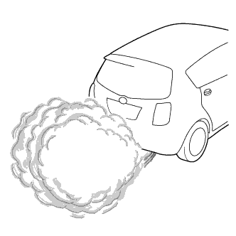 |
Check whether white smoke is emitted or not when racing the engine.
| Result | Proceed to |
| White smoke is emitted | A |
| White smoke is not emitted | B |
|
| ||||
| A | |
|
| 4.READ OUTPUT DTC (RELATED TO ENGINE) |
Connect the intelligent tester to the DLC3.
Turn the ignition switch ON and turn the tester ON.
Enter the following menus: Powertrain / Engine / DTC.
Read DTCs.
| Result | Proceed to |
| No DTCs are output | A |
| DTCs related to engine are output | B |
|
| ||||
| A | |
|
| 5.CHECK WHITE SMOKE (ACCORDING TO ENGINE CONDITION) |
|
Check whether the white smoke is emitted only just after engine start and disappears later, or not.
| Result | Proceed to |
| Yes (white smoke is emitted only just after engine start) | A |
| No (white smoke is always and continuously emitted) | B |
|
| ||||
| A | |
|
| 6.CHECK TEMPERATURE WHEN WHITE SMOKE IS EMITTED |
Check whether the white smoke is emitted only in cold weather when the temperature is less than 0°C (32°F).
| Result | Proceed to |
| Yes (white smoke is emitted in only cold conditions) | A |
| No (white smoke is emitted in both cold and warm conditions) | B |
|
| ||||
| A | |
|
| 7.INSPECT GLOW PLUG ASSEMBLY (RESISTANCE) |
Inspect the glow plug assembly .
|
| ||||
| OK | |
|
| 8.CHECK INJECTOR COMPENSATION CODE |
Read the injector compensation codes (Click here).
|
| ||||
| OK | |
|
| 9.CHECK FUEL SYSTEM (DIESEL INJECTION SYSTEM) |
Check the fuel system (Click here).
|
| ||||
| OK | |
|
| 10.CHECK ELECTRIC EGR CONTROL VALVE ASSEMBLY |
Connect the intelligent tester to the DLC3.
Turn the ignition switch to ON and turn the tester ON.
Enter the following menus: Powertrain / Engine / Data List / EGR Close Lrn. Status.
Read the value.
Start the engine and warm it up, and make sure the A/C switch and all accessory switches are off.
Turn the ignition switch off. Wait for 30 seconds, and then restart the engine.
Turn the tester ON.
Enter the following menus: Powertrain / Engine / Data List / MAF and MAP.
Read the MAF and/or MAP values displayed on the tester while the engine is idling.
Enter the following menus: Powertrain / Engine / Active Test / Activate the VSV for EGR Cut, Control the EGR System, or Activate the VSV for EGR Close*.
Read the MAF and/or MAP values when the Active Test is performed.
Remove the electric EGR control valve assembly (Click here).
Visually check the EGR valve for deposits. If there are deposits, clean the EGR valve and EGR passage (intake/exhaust manifold, EGR cooler, EGR pipes, etc.).
Hold the EGR valve up to a light, and visually check that there is no gap between the valve and body.
|
| ||||
| OK | |
|
| 11.CHECK CYLINDER COMPRESSION PRESSURE |
Check the cylinder compression pressure .
|
| ||||
| OK | |
|
| 12.REPLACE TURBOCHARGER SUB-ASSEMBLY |
Replace the turbocharger sub-assembly (Click here).
| NEXT | |
|
| 13.CONFIRM WHETHER MALFUNCTION HAS BEEN SUCCESSFULLY REPAIRED |
Check whether the white smoke problem has been successfully repaired by starting the engine.
| NEXT | ||
| ||
| ||
| 14.INSPECT COMPRESSOR INLET |
Remove the air cleaner hose from the compressor inlet (remove the compressor inlet elbow if necessary).
Check whether an excessive amount of oil is present or not, and whether excessive oil deposits are attached to the compressor impeller or not.
Reinstall the air cleaner hose (compressor inlet elbow).
| NEXT | |
|
| 15.INSPECT COMPRESSOR OUTLET |
Remove the air hose from the compressor outlet.
Check whether or not an excessive amount of oil or excessive oil deposits are present at the compressor outlet.
| Result | Proceed to |
| Excessive amount of oil present at both compressor inlet and outlet | C |
| Excessive amount of oil present only at compressor outlet | B |
| Excessive amount of oil not present at compressor inlet and outlet | A |
Reinstall the air hose.
|
| ||||
|
| ||||
| A | |
|
| 16.INSPECT TURBINE INLET |
Remove the turbocharger from the engine.
Check whether an excessive amount of wet oil or excessive oil deposits are present at the turbine inlet.
| NEXT | |
|
| 17.INSPECT TURBINE OUTLET |
Check whether an excessive amount of wet oil or excessive oil deposits are present at the turbine outlet.
| Result | Proceed to |
| Excessive amount of oil present at both turbine inlet and outlet | B |
| Excessive amount of oil present only at turbine outlet | A |
|
| ||||
| A | |
|
| 18.REPLACE TURBOCHARGER SUB-ASSEMBLY |
Replace the turbocharger sub-assembly (Click here).
| NEXT | |
|
| 19.CONFIRM WHETHER MALFUNCTION HAS BEEN SUCCESSFULLY REPAIRED |
Check whether the oil leakage problem has been successfully repaired.
| NEXT | ||
| ||
| ||

