Home › ENGINE ยท 2TR-FE › LUBRICATION › OIL PUMP

OIL PUMP > INSTALLATION

for Preparation Click here


1. INSTALL TIMING CHAIN COVER OIL SEAL


    A097898E01
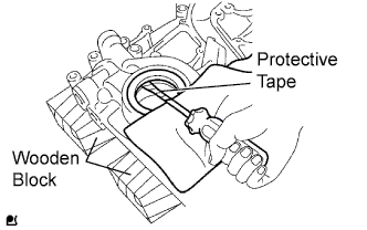
  1. Place the timing chain cover on wooden blocks.

  1. Using a screwdriver with its tip taped, pry out the oil seal.


    A172563E01
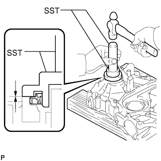
  1. Using SST and a hammer, tap in a new oil seal until its surface is flush with the timing chain cover edge.

    SST
    09223-75010  
    09950-70010   (09951-07150)

    NOTICE:
    1. Keep the lip free from foreign matter.
    2. Do not tap the oil seal at an angle.

    HINT:
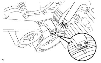
    When installing the crankshaft pulley, check the shape of the pulley. The correct pulley has a groove .

  1. Apply a light coat of MP grease to the lip of the oil seal.


2. INSTALL WATER PUMP ASSEMBLY


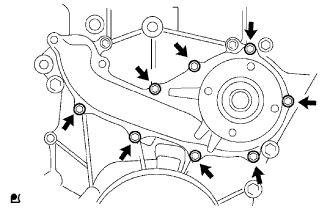
    A087223E01
  1. Install a new gasket and the water pump with the 8 bolts.

    Torque:
    13 N*m{ 133 kgf*cm , 10 ft.*lbf }


3. INSTALL TIMING CHAIN COVER (OIL PUMP ASSEMBLY)


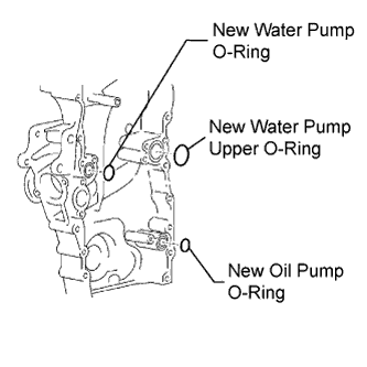
    A116074E01
  1. Install 3 new O-rings to the timing chain cover as shown in the illustration.


    A058128E06
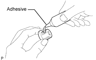
  1. Apply adhesive to the timing gear case plug.
    Adhesive:
    Toyota Genuine Adhesive 1324, Three Bond 1324 or equivalent


    G036021E01
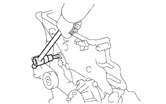
  1. Using a 10 mm socket hexagon wrench, install the timing gear case plug.

    Torque:
    16.6 N*m{ 169 kgf*cm , 12 ft.*lbf }


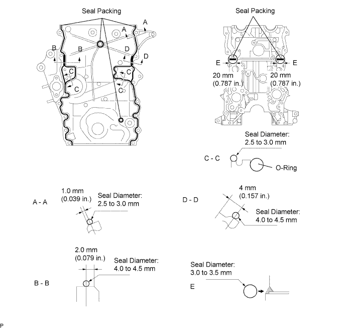
  1. Apply seal packing in a continuous line as shown in the illustration.

    Seal packing:
    Toyota Genuine Seal Packing Black, Three Bond 1207B or equivalent

    Standard seal diameter:
    Position
    Specified Condition
    A - A, C - C
    2.5 to 3.0 mm (0.098 to 0.118 in.)
    B - B, D - D
    4.0 to 4.5 mm (0.157 to 0.177 in.)
    E
    3.0 to 3.5 mm (0.118 to 0.138 in.)

    NOTICE:
    1. Remove any oil from the contact surface.
    2. Install the timing chain cover within 3 minutes and tighten the bolts within 15 minutes after applying seal packing.
    3. Do not start the engine for at least 4 hours after the installation.


    G038474E02


    G038475E02
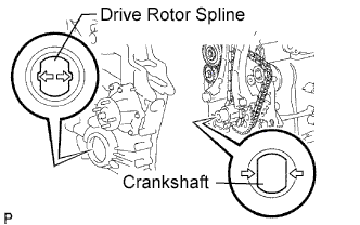
  1. Align the oil pump's drive rotor spline and crankshaft as shown in the illustration. Install the spline and chain cover plate to the crankshaft.

  1. Loosely install the timing chain cover with the 19 bolts and 2 nuts, but do not tighten the bolts and nuts yet.

  1. Excluding the bolts labeled A and C, tighten the bolts and nuts in this order: Area 1, Area 2 and Area 3.

    Torque:
    21 N*m{ 214 kgf*cm , 15 ft.*lbf }

    Bolt Length:
    Item
    Length
    Thread Diameter
    Bolt A
    75 mm (2.95 in.)
    10 mm (0.394 in.)
    Bolt B
    75 mm (2.95 in.)
    8 mm (0.315 in.)
    Bolt C
    90 mm (3.54 in.)
    8 mm (0.315 in.)
    Bolt D
    95 mm (3.74 in.)
    8 mm (0.315 in.)
    Bolt E
    35 mm (1.38 in.)
    8 mm (0.315 in.)
    Bolt F
    75 mm (2.95 in.)
    10 mm (0.394 in.)

  1. Excluding the bolts labeled A, E and F, tighten the bolts and nuts in this order: Area 1, Area 3, Area 2.

    Torque:
    for bolt C:
    26 N*m{ 265 kgf*cm , 19 ft.*lbf }
    for bolt B, D and nut:
    21 N*m{ 214 kgf*cm , 15 ft.*lbf }

  1. Tighten the bolts labeled A in this order: Area 2 and Area 3.

    Torque:
    60 N*m{ 612 kgf*cm , 44 ft.*lbf }

  1. Tighten the bolt labeled F.

    Torque:
    46 N*m{ 469 kgf*cm , 34 ft.*lbf }


  1. Tighten the bolts labeled E in Area 4.
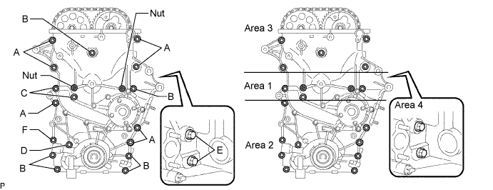
    Torque:
    21 N*m{ 214 kgf*cm , 15 ft.*lbf }


    G037337E09


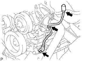
4. INSTALL CRANKSHAFT POSITION SENSOR


    A099147E04
  1. Apply a light coat of engine oil to the O-ring of the sensor.

  1. Install the sensor with the bolt.

    Torque:
    8.5 N*m{ 87 kgf*cm , 75 in.*lbf }

  1. Install the connector to the connector bracket.

  1. Attach the harness clamp.

  1. Connect the sensor connector.


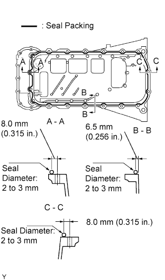
5. INSTALL NO. 1 OIL PAN SUB-ASSEMBLY
  1. Install the O-ring.


    G038861E03
  1. Apply seal packing in a continuous line as shown in the illustration.
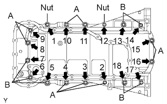
    Seal packing:
    Toyota Genuine Seal Packing Black, Three Bond 1207B or equivalent

    Standard seal diameter:
    2 to 3 mm (0.079 to 0.118 in.)

    NOTICE:
    1. Remove any oil from the contact surface.
    2. Install the oil pan within 3 minutes after applying seal packing.
    3. Do not start the engine for at least 4 hours after the installation.


    A099220E03
  1. Temporarily install the oil pan with the 16 bolts and 2 nuts.

    HINT:
    Bolt length:
    20 mm (0.79 in.) for bolt A
    40 mm (1.57 in.) for bolt B

  1. Uniformly tighten the 16 bolts and 2 nuts in the order shown in the illustration.

    Torque:
    26 N*m{ 265 kgf*cm , 19 ft.*lbf }


6. INSTALL OIL STRAINER SUB-ASSEMBLY
  1. Install a new gasket and the oil strainer with the bolt and 2 nuts.

    Torque:
    20 N*m{ 204 kgf*cm , 15 ft.*lbf }


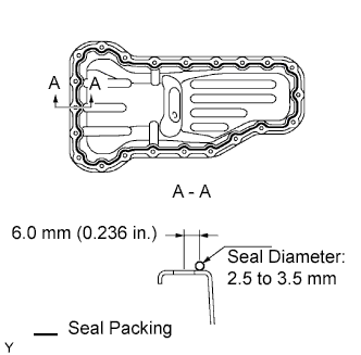
7. INSTALL NO. 2 OIL PAN SUB-ASSEMBLY


    A099221E04
  1. Apply seal packing in a continuous line as shown in the illustration.
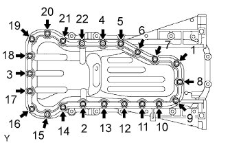
    Seal packing:
    Toyota Genuine Seal Packing Black, Three Bond 1207B or equivalent

    Standard seal diameter:
    2.5 to 3.5 mm (0.098 to 0.138 in.)

    NOTICE:
    1. Remove any oil from the contact surface.
    2. Install the oil pan within 3 minutes after applying seal packing.
    3. Do not start the engine for at least 4 hours after the installation.


    A099214E03
  1. Temporarily install the oil pan with the 20 bolts and 2 nuts.

  1. Uniformly tighten the 20 bolts and 2 nuts in the order shown in the illustration.

    Torque:
    9.0 N*m{ 92 kgf*cm , 80 in.*lbf }

  1. Install a new gasket and the drain plug.

    Torque:
    37.5 N*m{ 382 kgf*cm , 28 ft.*lbf }


8. INSTALL CRANKSHAFT PULLEY
  1. Align the pulley set key with the key groove of the pulley, and slide on the pulley.
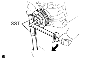


    A097885E02
  1. Using SST, install a new crankshaft pulley bolt.

    SST
    09213-54015   (91651-60855)
    09330-00021  

    Torque:
    260 N*m{ 2651 kgf*cm , 192 ft.*lbf }

    NOTICE:
    Do not reuse the pulley bolt.


9. INSTALL CAMSHAFT POSITION SENSOR
  1. Apply a coat of engine oil to a new O-ring.

  1. Install the sensor with the bolt.

    Torque:
    8.5 N*m{ 87 kgf*cm , 75 in.*lbf }


10. INSTALL CYLINDER HEAD COVER SUB-ASSEMBLY
  1. Install the 2 cover gaskets to the head cover.
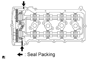


    A099825E03
  1. Apply seal packing to the places shown in the illustration.
    Seal packing:
    Toyota Genuine Seal Packing Black, Three Bond 1207B or equivalent

    NOTICE:
    1. Remove any oil from the contact surface.
    2. Install the head cover within 3 minutes after applying seal packing.
    3. Do not start the engine for at least 2 hours after the installation.


    A088646E01
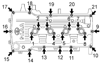
  1. Temporarily install the head cover with the 19 bolts and 2 nuts.

  1. Uniformly tighten the 19 bolts and 2 nuts in the order shown in the illustration.

    Torque:
    9.0 N*m{ 92 kgf*cm , 80 in.*lbf }

  1. In numerical order, confirm that the bolts labeled 1 to 8 are tightened to the torque specification. Tighten the bolts as necessary.


11. INSTALL OIL FILLER CAP


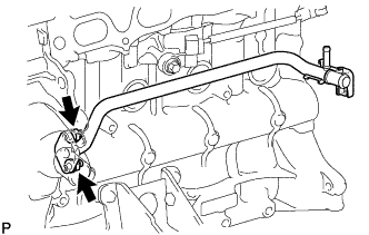
12. INSTALL NO. 1 WATER BY-PASS PIPE


    A289060
  1. Install a new gasket and the water by-pass pipe with the 2 nuts.

    Torque:
    17.5 N*m{ 178 kgf*cm , 13 ft.*lbf }


13. INSTALL NO. 1 IDLER PULLEY SUB-ASSEMBLY
  1. Install the spacer, idler pulley and pulley plate with the bolt.

    Torque:
    43 N*m{ 438 kgf*cm , 32 ft.*lbf }


14. INSTALL DRIVE BELT TENSIONER ASSEMBLY
  1. Temporarily install the belt tensioner with the 3 bolts.
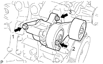
    HINT:
    Make sure that the flanges of the bolts are contacting the tensioner surface.


    G035081E04
  1. Install the tensioner by tightening the 3 bolts in the order shown in the illustration.

    Torque:
    40 N*m{ 408 kgf*cm , 30 ft.*lbf } for bolt 1
    21 N*m{ 214 kgf*cm , 15 ft.*lbf } for bolt 2
    43 N*m{ 438 kgf*cm , 32 ft.*lbf } for bolt 3


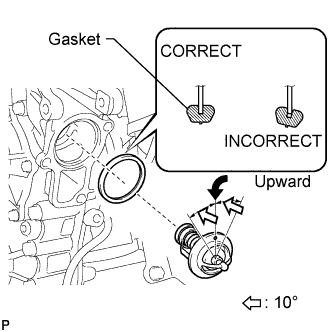
15. INSTALL THERMOSTAT


    A110369E02
  1. Install a new gasket to the thermostat.

    HINT:
    When installing the thermostat to the gasket, be careful not to deform the gasket. Make sure that the thermostat is properly installed into the groove of the gasket, as shown in the illustration.

  1. Insert the thermostat into the cylinder block with the jiggle valve facing straight upward.

    HINT:
    The jiggle valve may be set within 10° of either side of the prescribed position.


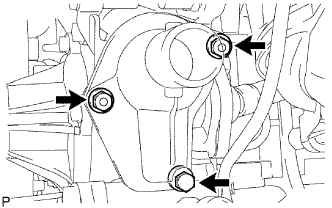
16. INSTALL WATER INLET


    A120284E01
  1. Install the inlet with the 2 nuts and bolt.
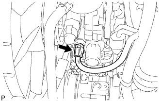
    Torque:
    20 N*m{ 204 kgf*cm , 15 ft.*lbf }


    A099676E01
  1. Connect the connector.


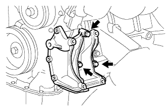
17. INSTALL COMPRESSOR MOUNTING BRACKET

NOTICE:
Install the compressor mounting bracket exactly as described in the procedures below to properly secure and prevent damage to the drive belt.


    A330624
  1. Temporarily install the compressor mounting bracket with the 3 bolts.

    HINT:
    Temporarily install the compressor mounting bracket with the 3 bolts so that the bracket can be moved by hand.


  1. Push the compressor mounting bracket toward the cylinder block as shown in the illustration and tighten bolt B.
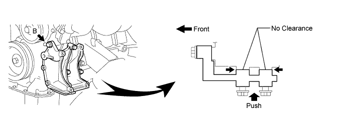
    A332516E01

    Torque:
    45 N*m{ 459 kgf*cm , 33 ft.*lbf } for bolt B

    HINT:
    Make sure there is no clearance between the cylinder block and compressor mounting bracket as shown in the illustration.


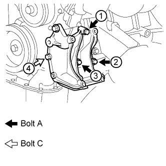
    A332517E01
  1. Uniformly tighten the 4 bolts in the order shown in the illustration.

    Torque:
    45 N*m{ 459 kgf*cm , 33 ft.*lbf } for bolt A
    24.5 N*m{ 250 kgf*cm , 18 ft.*lbf } for bolt C


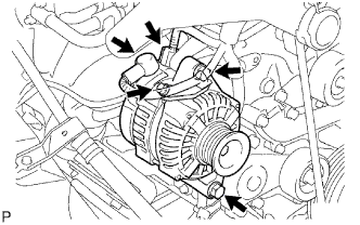
18. INSTALL GENERATOR ASSEMBLY


    A099681E03
  1. Install the generator with the 2 bolts.

    Torque:
    43 N*m{ 438 kgf*cm , 32 ft.*lbf }

  1. Install the generator wire with the bolt and nut.

    Torque:
    9.8 N*m{ 100 kgf*cm , 87 in.*lbf }

  1. Attach the terminal cap.

  1. Connect the connector.


19. INSTALL INTAKE MANIFOLD


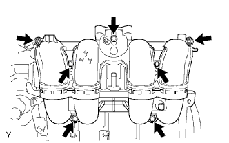
G036020E01
  1. Install a new gasket and the intake manifold with the 5 bolts and 2 nuts.

    Torque:
    25 N*m{ 255 kgf*cm , 18 ft.*lbf }

  1. Connect the crankshaft position sensor to the clamp.


20. INSTALL THROTTLE BODY ASSEMBLY


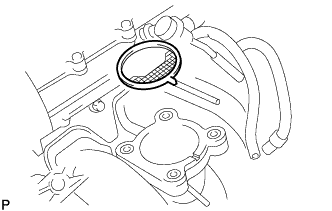
    A306999
  1. Install a new gasket on the intake manifold.
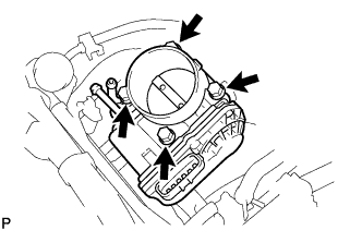
    HINT:
    Align the protrusion of the gasket with the groove of the intake manifold.


    A309649
  1. Install the throttle body with the 4 bolts.

    Torque:
    9.0 N*m{ 92 kgf*cm , 80 in.*lbf }

  1. Connect the 2 water by-pass hoses to the throttle body.

  1. Connector the throttle position sensor and control motor connector.


21. INSTALL SPARK PLUG


22. INSTALL IGNITION COIL ASSEMBLY
  1. Install the ignition coil with the bolt.

    Torque:
    9.0 N*m{ 92 kgf*cm , 80 in.*lbf }


23. REMOVE ENGINE ASSEMBLY FROM ENGINE STAND


24. INSTALL ENGINE ASSEMBLY
  1. Install the engine to the vehicle (Click here).


25. CONNECT CABLE TO NEGATIVE BATTERY TERMINAL


26. ADD ENGINE OIL
  1. Clean and install the oil drain plug with a new gasket.

    Torque:
    37.5 N*m{ 382 kgf*cm , 28 ft.*lbf }

  1. Add fresh engine oil.

    Standard capacity:
    Item
    Specified Condition
    Drain and refill with oil filter change
    5.6 liters (5.9 US qts, 4.9 Imp. qts)
    Drain and refill without oil filter change
    5.3 liters (5.6 US qts, 4.6 Imp. qts)
    Dry fill
    6.3 liters (6.7 US qts, 5.5 Imp. qts)

  1. Install the oil filler cap.


27. ADD ENGINE COOLANT
  1. Tighten all the plugs and fill the radiator with TOYOTA Super Long Life Coolant (SLLC).

    Torque:
    13 N*m{ 130 kgf*cm , 9 ft.*lbf } for cylinder block drain cock plug

    Standard capacity:
    8.1 liters (8.6 US qts, 7.1 Imp. qts)

  1. Fill the radiator with TOYOTA SLLC to the F line.

    HINT:
    1. TOYOTA vehicles are filled with TOYOTA SLLC at the factory. In order to avoid damage to the engine cooling system and other technical problems, only use TOYOTA SLLC or similar high quality ethylene glycol based non-silicate, non-amine, non-nitrite, non-borate coolant with long-life hybrid organic acid technology (coolant with long-life hybrid organic acid technology consists of a combination of low phosphates and organic acids).
    2. Please contact your TOYOTA dealer for further details.

      NOTICE:
      Never use water as a substitute for engine coolant.

  1. Press the inlet and outlet radiator hoses several times by hand, and then check the level of the coolant.
    If the coolant level drops below the F line, add TOYOTA SLLC to the F line.

  1. Install the radiator cap.

  1. Bleed air from the cooling system.

    1. Warm up the engine until the thermostat opens. While the thermostat is open, circulate the coolant for several minutes.

    2. Maintain the engine speed at 2,500 to 3,000 rpm.

    3. Press the inlet and outlet radiator hoses several times by hand to bleed air.

      CAUTION:
      When pressing the radiator hoses:
      1. Wear protective gloves.
      2. Be careful as the radiator hoses are hot.
      3. Keep your hands away from the radiator fan.

  1. Stop the engine and wait until the coolant cools down to ambient temperature.
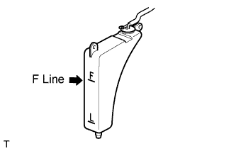
    CAUTION:
    Do not remove the radiator cap while the engine and radiator are still hot. Pressurized, hot engine coolant and steam may be released and cause serious burns.


    A112081E01
  1. Check the coolant level in the radiator reservoir.
    If the coolant level is below the L line, add SLLC to the reservoir F line.


28. INSPECT FOR FUEL LEAK
  1. Connect the intelligent tester to the DLC3.

    1. Turn the ignition switch ON.

      NOTICE:
      Do not start the engine.

    2. Push the intelligent tester main switch ON.

    3. Select the Active Test and enter the following menus: Powertrain / Engine and ECT / Active Test / Control the Fuel Pump / Speed.

  1. Check for fuel leaks.

    1. Check that there are no fuel leaks after performing maintenance anywhere on the fuel system.
      If there are fuel leaks, repair or replace parts as necessary.


29. INSPECT FOR OIL LEAK
  1. Start the engine, and check that there are no oil leaks after performing maintenance.


30. INSPECT FOR COOLANT LEAK
  1. Check for engine coolant leaks .


31. CHECK FUNCTION OF THROTTLE BODY


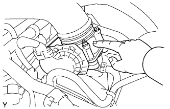
    A111693
  1. Check the throttle control motor operating sound.

    1. Turn the ignition switch ON.

    2. When pressing the accelerator pedal, check the operating sound of the running motor. Make sure that no friction noises emit from the motor.
      If friction noise is heard, replace the throttle body.
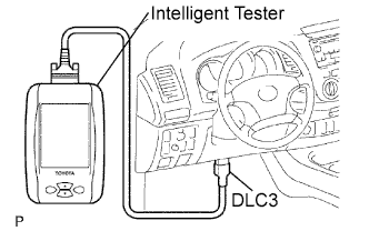


    A099015E01
  1. Check the throttle position sensor.

    1. Connect the intelligent tester to the DLC3.

    2. Turn the ignition switch ON.

    3. Under Current Data, check that the throttle valve opening percentage (Throttle Pos) is within the standard.

      Standard throttle valve opening percentage:
      60% or more

      NOTICE:
      When checking the standard throttle valve opening percentage, the shift lever should be in the N position.

      If the percentage is less than 60%, replace the throttle body.


32. CHECK IGNITION TIMING
  1. Warm up the engine and stop the engine.
    NOTICE:
    A warmed up engine should have an engine coolant temperature of over 80°C (176°F), have an engine oil temperature of 60°C (140°F), and the engine rpm should be stabilized.


    C108852E03
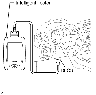
  1. When using the intelligent tester:
    Check the ignition timing.

    1. Connect the intelligent tester to the DLC3.

    2. Start the engine and idle the engine.

    3. Turn the intelligent tester main switch ON.

    4. Enter the following menus: Powertrain / Engine and ECT / Data List / IGN Advance.
      Standard ignition timing:
      0 to 20° BTDC @ idle

      HINT:
      Please refer to the intelligent tester operator's manual for further details.


    H100769E32
  1. When not using the intelligent tester:
    Check the ignition timing.

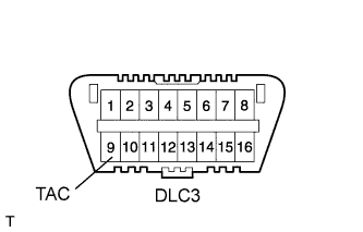
    1. Using SST, connect a tachometer tester probe to terminal 9 (TAC) of the DLC3.
      SST
      09843-18030  

      NOTICE:
      1. Confirm the terminal number before connecting SST. Connection with a wrong terminal can damage the engine.
      2. Turn off all electrical systems before connecting SST.


    2. A099874E01
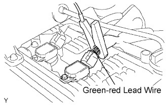
    3. Clamp a timing light tester probe to the No. 1 cylinder ignition coil connector's 4 lead wires or green-red lead wire.

    4. Start the engine.


    5. H100769E09
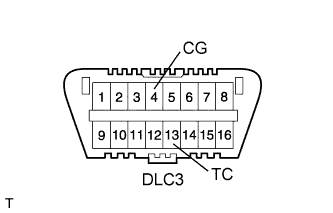
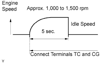
    6. Using SST, connect terminals 13 (TC) and 4 (CG) of the DLC3.
      SST
      09843-18040  

      NOTICE:
      When checking the ignition timing, the transmission should be in the neutral position.


      HINT:
      A099876E01
      1. After connecting terminals TC and CG, the engine rpm changes to approximately 1,000 to 1,500 rpm for 5 seconds, and then returns to idle speed. This occurs because the ECM checks that the ISC (idle speed control system) is operating properly.
      2. Perform the inspection of the ignition timing after the engine rpm has returned to idle speed.


    7. A099880E01
    8. Using a timing light, measure the ignition timing.

      Standard ignition timing:
      3 to 7° BTDC @ idle

    9. Remove SST from terminals 13 (TC) and 4 (CG) of the DLC3.

    10. Check the ignition timing.

      Standard ignition timing:
      0 to 20° BTDC @ idle

    11. Confirm that the ignition timing moves to the advanced angle side when the engine speed is increased.

    12. Remove the timing light.


33. CHECK ENGINE IDLE SPEED
  1. Warm up and stop the engine.

    NOTICE:
    A warmed up engine should have an engine coolant temperature of over 80°C (176°F), have an engine oil temperature of 60°C (140°F), and the engine rpm should be stabilized.


  1. When using the intelligent tester:
    Check the idle speed.


      C108852E03
    1. Connect the intelligent tester to the DLC3.

      HINT:
      Please refer to the intelligent tester operator's manual for further details.

    2. Start the engine and idle the engine.

    3. Turn the intelligent tester main switch ON.

    4. Enter the following menus: Powertrain / Engine and ECT / Data List / Engine SPD.

      Standard idle speed:
      600 to 700 rpm

      NOTICE:
      1. When checking the idle speed, the transmission should be in the neutral position.
      2. Switch off all accessories and the air conditioning before connecting the intelligent tester.


    H100769E32
  1. When not using the intelligent tester:
    Check the idle speed.

    1. Using SST, connect a tachometer tester probe to terminal 9 (TAC) of the DLC3.

      SST
      09843-18030  

      NOTICE:
      1. Confirm the terminal number before connecting SST. Connection with a wrong terminal can damage the engine.
      2. Turn off all electrical systems before connecting SST.

    2. Start the engine and idle the engine.

    3. Check the idle speed.

      Standard idle speed:
      600 to 700 rpm


34. CHECK CO/HC
  1. Start and warm up the engine.

  1. Run the engine at 2,500 rpm for approximately 180 seconds and idle the engine.


    G038860E01
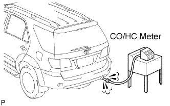
  1. Insert a CO/HC meter testing probe at least 40 cm (1.3 ft.) into the tailpipe.

  1. Check the CO/HC concentration at idle.

    Idle CO concentration:
    0 to 0.5%

    Idle HC concentration:
    Applicable local regulation

  1. If the CO/HC concentration is not as specified, perform troubleshooting in the order given below.

    1. Check the heated oxygen sensor operation (Click here).

    2. See the table below for possible causes, and then inspect and repair the applicable causes as necessary.

      CO
      HC
      Problems
      Causes
      Normal
      High
      Rough idle
      1. Faulty ignitions:
        1. Incorrect timing
        2. Plugs are contaminated, shorted or gaps are defective
      2. Incorrect valve clearance
      3. Leaks in intake and exhaust valves
      4. Leaks in cylinders
      Low
      High
      Rough idle
      (Fluctuating HC reading)
      1. Vacuum leaks:
        1. Ventilation hoses
        2. Intake manifold
        3. Throttle body
        4. Brake booster line
      2. Lean mixture causing misfire
      High
      High
      Rough idle
      (Black smoke from exhaust)
      1. Restricted air filter
      2. Plugged ventilation valve
      3. Faulty SFI system:
        1. Faulty pressure regulator
        2. Defective ECT sensor
        3. Defective Mass Air Flow (MAF) meter
        4. Faulty ECM
        5. Faulty injectors
        6. Faulty throttle position sensor