REAR AXLE SHAFT > INSTALLATION |
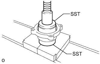
| 1. INSTALL REAR AXLE SHAFT BEARING LH |
|
Using SST and a press, press in a new bearing.
| 2. INSTALL REAR AXLE SHAFT OUTER OIL SEAL |
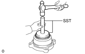 |
Using SST and a hammer, tap in a new oil seal.
| 3. INSTALL REAR AXLE HUB BOLT LH |
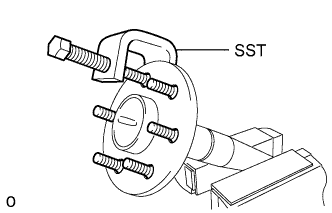 |
Install a new gasket and the deflector to the axle shaft.
Pass 6 new hub bolts through the axle hub.
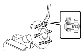 |
Secure the axle shaft between aluminum plates in a vise.
Temporarily install a washer and nut to each of the 6 hub bolts as shown in the illustration.
Install the hub bolts by tightening each nut.
Remove the washer and nut from each hub bolt.
| 4. INSTALL BACKING PLATE TO REAR AXLE HOUSING SETTING BOLT |
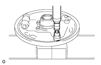 |
Position the backing plate on the bearing case.
Using 2 socket wrenches and a press, press in 4 new setting bolts.
| 5. INSTALL REAR AXLE BEARING INNER RETAINER LH |
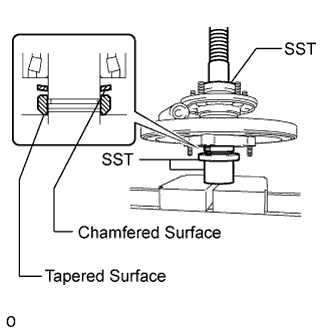 |
Heat a new retainer to approximately 70 to 130°C (158 to 266°F).
Install a new shaft washer and the retainer to the axle shaft as shown in the illustration.
Using SST and a press, press in the axle shaft.
Using a snap ring expander, install a new snap ring.
| 6. INSTALL REAR AXLE BEARING INNER RETAINER LH AND REAR SKID CONTROL ROTOR (w/ ABS, VSC) |
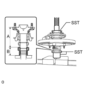 |
Using SST and a press, press in a new skid control rotor and retainer to the axle shaft until the lengths are within the standard range.
| Length A | Length B |
| 133.2 +/-0.6 mm (5.244 +/-0.0236 in.) | 56 mm (2.205 in.) |
| 7. INSTALL REAR AXLE SHAFT OIL SEAL LH |
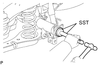 |
Using SST and a hammer, tap in a new oil seal.
| 8. INSTALL O-RING |
Install a new O-ring to the axle housing.
| 9. INSTALL REAR AXLE SHAFT WITH BACKING PLATE |
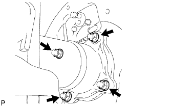 |
Install the axle shaft with backing plate with the 4 nuts.
| 10. CONNECT PARKING BRAKE CABLE |
Connect the parking brake cable with the 2 bolts.
| 11. INSTALL BRAKE SHOES |
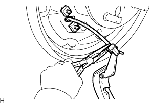 |
Using needle-nose pliers, connect the No. 3 parking brake cable to the parking brake shoe lever.
Install the strut set and return spring to the shoe.
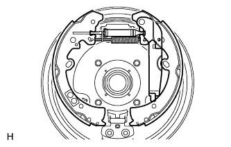 |
Attach the support clip to the exposed threads of the strut set.
Using needle-nose pliers, hook the support clip around the spring.
Install the front and rear brake shoes.
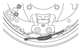 |
Move one of the shoes upward and install the shoe tension spring.
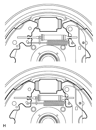 |
Install the shoe front or rear side to the cylinder. Then install the other side of the shoe to the other side of the cylinder.
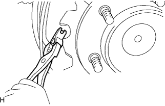 |
Using pliers, install the front brake shoe, rear brake shoe, pins and shoe hold down springs.
| 12. INSTALL REAR SPEED SENSOR LH (w/ ABS, VSC) |
Install the speed sensor with the bolt.
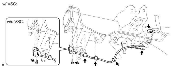
Attach the 3 clamps.
Connect the connector.
Attach the connector.
| 13. CONNECT BRAKE LINE |
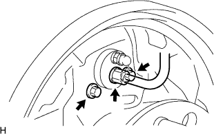 |
Install the cylinder with the 2 bolts.
Using a union nut wrench, connect the brake line.
| 14. INSTALL REAR BRAKE DRUM SUB-ASSEMBLY |
| 15. FILL RESERVOIR WITH BRAKE FLUID (w/ VSC) |
| 16. FILL RESERVOIR WITH BRAKE FLUID (w/o VSC) |
| 17. BLEED AIR FROM BRAKE LINE (w/ VSC) |
Remove the bleeder plug cap.
Connect a vinyl tube to the bleeder plugs.
Depress the pedal several times, and then loosen the bleeder plug with the pedal depressed.
When fluid stops coming out, immediately tighten the bleeder plug. Then release the pedal.
Repeat the 2 previous steps until all the air in the brake fluid is gone.
Tighten the bleeder plug.
Install the cap.
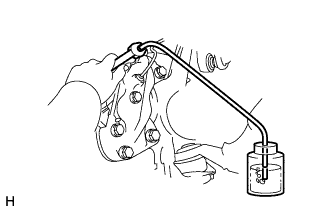 |
Bleed air from the brake line for each wheel by repeating the above procedures.
| 18. BLEED AIR FROM BRAKE LINE (w/o VSC) |
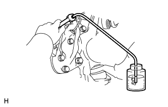 |
Remove the bleeder plug cap.
Connect a vinyl tube to the bleeder plugs.
Depress the brake pedal several times, and then loosen the bleeder plug with the pedal depressed.
When fluid stops coming out, immediately tighten the bleeder plug. Then release the pedal.
Repeat the 2 previous steps until all the air in the brake fluid is gone.
Tighten the bleeder plug.
Install the cap.
Bleed air from the brake line for each wheel by repeating the above procedures.
| 19. CHECK BRAKE FLUID LEVEL IN RESERVOIR |
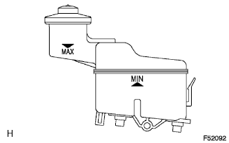 |
Check the fluid level and add fluid if necessary.
| 20. CHECK FOR BRAKE FLUID LEAKAGE |
| 21. INSTALL REAR WHEEL |
| 22. CHECK PARKING BRAKE LEVER TRAVEL |
Pull the lever upward with a force of approximately 200 N (20 kgf, 45 lbf) and count the number of clicks.
| 23. ADJUST PARKING BRAKE LEVER TRAVEL |
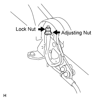 |
Turn the No. 1 wire adjusting nut until the lever travel is correct.
Tighten the lock nut.
| 24. CONNECT CABLE TO NEGATIVE BATTERY TERMINAL |
| 25. PERFORM INITIALIZATION |
Perform initialization (Click here).
| 26. CHECK SPEED SENSOR SIGNAL |
w/o VSC:
Check the speed sensor signal (Click here).
w/ VSC:
Check the speed sensor signal (Click here).