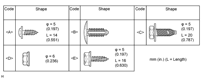
All bolts, screws, nuts and clips relevant to installing and removing the instrument panel are shown along with an alphabetical code in the table.
LOWER INSTRUMENT PANEL > REMOVAL |
| 1. TABLE OF BOLT, SCREW AND NUT |
All bolts, screws, nuts and clips relevant to installing and removing the instrument panel are shown along with an alphabetical code in the table.
| 2. PRECAUTION |
| 3. DISCONNECT CABLE FROM NEGATIVE BATTERY TERMINAL |
| 4. REMOVE UPPER INSTRUMENT PANEL SUB-ASSEMBLY |
| 5. REMOVE HEADLIGHT DIMMER SWITCH ASSEMBLY |
| 6. REMOVE CONSOLE BOX ASSEMBLY |
| 7. REMOVE FRONT DOOR SCUFF PLATE LH |
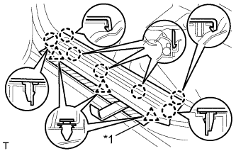 |
Put protective tape around the front door scuff plate.
| *1 | Protective Tape |
Using a moulding remover, detach the 7 claws and 3 clips and remove the front door scuff plate.
| 8. REMOVE FRONT DOOR SCUFF PLATE RH |
| 9. REMOVE COWL SIDE TRIM BOARD LH |
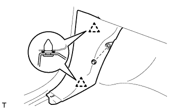 |
Remove the part of the front door opening trim attached to the cowl side trim board.
Remove the clip.
Detach the 2 clips and remove the cowl side trim board.
| 10. REMOVE COWL SIDE TRIM BOARD RH |
| 11. REMOVE NO. 2 HEATER TO REGISTER DUCT |
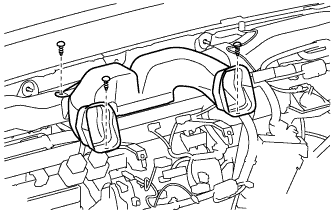 |
Remove the 3 clips and No. 2 heater to register duct.
| 12. REMOVE NO. 1 HEATER TO REGISTER DUCT |
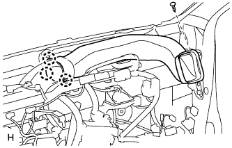 |
Remove the clip.
Detach the 3 claws and remove the No. 1 heater to register duct.
| 13. REMOVE NO. 3 HEATER TO REGISTER DUCT |
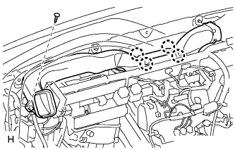 |
Remove the clip.
Detach the 4 claws and remove the No. 3 heater to register duct.
| 14. REMOVE LOWER INSTRUMENT PANEL FINISH PANEL SUB-ASSEMBLY |
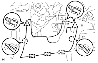 |
Detach the 2 claws, 3 clips and 3 guides and remove the lower instrument panel finish panel.
| 15. REMOVE NO. 1 INSTRUMENT PANEL BOX |
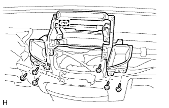 |
Remove the 6 screws <A>.
Disconnect the connectors, detach the clamp and remove the No. 1 instrument panel box.
| 16. REMOVE AIR CONDITIONER CONTROL ASSEMBLY (for Manual Air Conditioning System) |
Disconnect the connector and remove the air conditioning control assembly.
| 17. REMOVE SWITCH BASE |
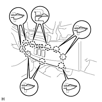 |
Detach the 9 claws and guide.
Disconnect the connectors and remove the switch base.
| 18. REMOVE NO. 1 SWITCH HOLE BASE |
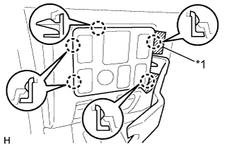 |
Put protective tape around the No. 1 switch hole base.
| *1 | Protective Tape |
Using a moulding remover, detach the 5 claws.
Disconnect the connectors and remove the No. 1 switch hole base.
| 19. REMOVE LOWER INSTRUMENT PANEL SUB-ASSEMBLY |
for LHD:
Using a clip remover, remove the 2 clips <B>.
Remove the 2 bolts <C>, nut <D> and 3 screws <E>.
Disconnect the hood lock control cable, fuel lid lock control cable and DLC3.
Disconnect the connectors and detach the clamps.
Detach the 2 guides and remove the lower instrument panel.
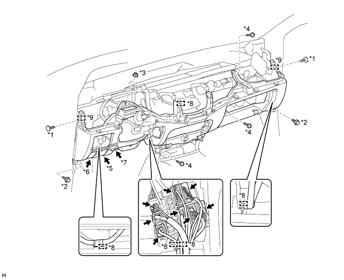
| *1 | Clip <B> | *2 | Bolt <C> |
| *3 | Nut <D> | *4 | Screw <E> |
| *5 | Hood Lock Control Cable | *6 | Fuel Lid Lock Control Cable |
| *7 | DLC3 | *8 | Clamp |
| *9 | Guide | - | - |
for RHD:
Using a clip remover, remove the 2 clips <B>.
Remove the 2 bolts <C>, nut <D> and 3 screws <E>.
Disconnect the hood lock control cable, fuel lid lock control cable and DLC3.
Disconnect the connectors and detach the clamps.
Detach the 2 guides and remove the lower instrument panel.
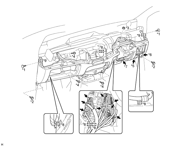
| *1 | Clip <B> | *2 | Bolt <C> |
| *3 | Nut <D> | *4 | Screw <E> |
| *5 | Hood Lock Control Cable | *6 | Fuel Lid Lock Control Cable |
| *7 | DLC3 | *8 | Clamp |
| *9 | Guide | - | - |