INSTALLATION
Removal / installation · Vehicles built Jun 2011 – Jul 2012
Versions by build date: Jun 2011 – Jul 2012 from Aug 2012
| 1. INSTALL NO. 2 TRANSMISSION HUB SLEEVE |

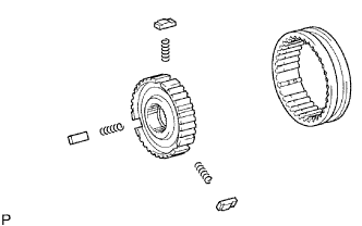  |
Install the 3 No. 2 synchromesh shifting key springs and 3 synchromesh shifting keys to the No. 2 clutch hub.
- NOTICE:
- Be careful of the direction of the No. 2 hub sleeve and that of the No. 2 clutch hub.
Apply gear oil to the sliding part of the No. 2 hub sleeve, and install it to the No. 2 clutch hub.
| 2. INSTALL 3RD GEAR NEEDLE ROLLER BEARING |
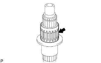 |
Apply gear oil to the needle roller bearing, and install it to the output shaft.
| 3. INSTALL 3RD GEAR |
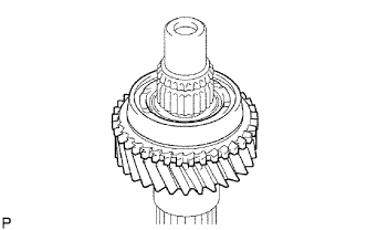 |
Apply gear oil to the 3rd gear, and install it to the output shaft.
| 4. INSTALL NO. 2 SYNCHRONIZER RING (FOR 3RD GEAR) |
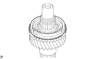 |
Apply gear oil to the No. 2 synchronizer ring, and install it to the 3rd gear.
| 5. INSTALL NO. 2 TRANSMISSION CLUTCH HUB |
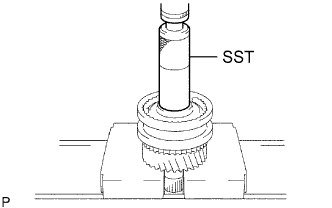 |
Using SST and a press, press in the No. 2 clutch hub to the output shaft.
- SST
- 09608-06041
- NOTICE:
- Install the hub while aligning the key groove of the hub and the shifting key position.
- The 3rd gear should be able to rotate smoothly.
- Install the hub while aligning the key groove of the hub and the shifting key position.
Select a snap ring that makes the clearance between the No. 2 clutch hub and snap ring to be within the specification.
- Standard clearance:
- 0.10 mm (0.0039 in.) or less
- NOTICE:
- Do not damage the sliding surface of the bearing.
Mark
Thickness
A
1.80 to 1.85 mm (0.0709 to 0.0728 in.)
B
1.85 to 1.90 mm (0.0728 to 0.0748 in.)
C
1.90 to 1.95 mm (0.0748 to 0.0768 in.)
D
1.95 to 2.00 mm (0.0768 to 0.0787 in.)
E
2.00 to 2.05 mm (0.0787 to 0.0807 in.)
F
2.05 to 2.10 mm (0.0807 to 0.0827 in.)
G
2.10 to 2.15 mm (0.0827 to 0.0846 in.)
Using a snap ring expander, install the snap ring.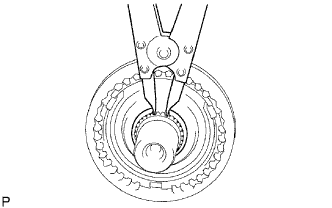
| 6. INSTALL 2ND GEAR NEEDLE ROLLER BEARING |
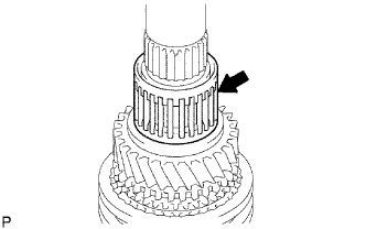 |
Apply gear oil to the needle roller bearing, and install it to the output shaft.
| 7. INSTALL 2ND GEAR |
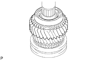 |
Apply gear oil to the 2nd gear, and install it to the output shaft.
| 8. INSTALL NO. 1 SYNCHRONIZER RING SET (FOR 2ND GEAR) |
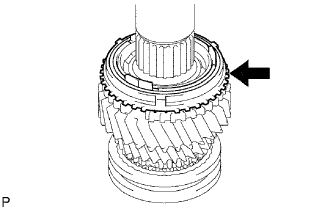 |
Apply gear oil to the No. 1 synchronizer ring set, and install it to the 2nd gear.
| 9. INSTALL REVERSE GEAR |
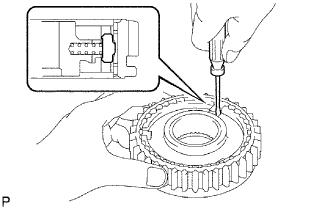 |
Using a screwdriver, install the 3 synchromesh shifting key springs and 3 No. 1 synchromesh shifting keys to the No. 1 clutch hub.
Apply gear oil to the reverse gear, and install it to the No. 1 clutch hub.
| 10. INSTALL NO. 1 TRANSMISSION CLUTCH HUB |
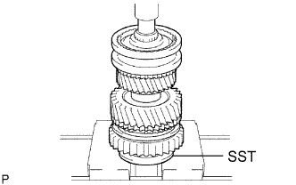 |
Using SST and a press, press in the No. 1 clutch hub to the output shaft.
- SST
- 09316-60011
(09316-00041)
- NOTICE:
- While performing (a) make sure that No. 1 synchronizer ring key groove and No. 1 synchromesh shifting key position are aligned.
- 1st gear should rotate freely.
- While performing (a) make sure that No. 1 synchronizer ring key groove and No. 1 synchromesh shifting key position are aligned.
Select a snap ring that makes the thrust clearance between the No. 1 clutch hub and snap ring to be within the specification.
- Standard clearance:
- 0.10 mm (0.0039 in.) or less
- NOTICE:
- Do not damage the sliding surface of the bearing.
Mark
Thickness
A
2.30 to 2.35 mm (0.0906 to 0.0925 in.)
B
2.35 to 2.40 mm (0.0925 to 0.0945 in.)
C
2.40 to 2.45 mm (0.0945 to 0.0965 in.)
D
2.45 to 2.50 mm (0.0965 to 0.0984 in.)
E
2.50 to 2.55 mm (0.0984 to 0.1004 in.)
F
2.55 to 2.60 mm (0.1004 to 0.1024 in.)
G
2.60 to 2.65 mm (0.1024 to 0.1043 in.)
Using a brass bar and a hammer, tap in the snap ring.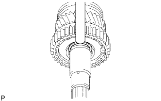
| 11. INSTALL 1ST GEAR BEARING SPACER |
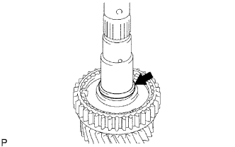 |
Apply gear oil to the bearing spacer, and install it to the output shaft.
| 12. INSTALL 1ST GEAR NEEDLE ROLLER BEARING |
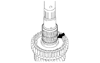 |
Apply gear oil to the needle roller bearing, and install it to the output shaft.
| 13. INSTALL 1ST GEAR THRUST WASHER PIN |
Install the thrust washer pin to the output shaft.
| 14. INSTALL NO. 1 SYNCHRONIZER RING SET (FOR 1ST GEAR) (1,2KD-FTV AND 1GR-FE) |
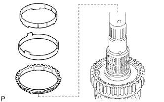 |
Apply gear oil to the No. 1 synchronizer ring set, and install them to the output shaft.
| 15. REMOVE NO. 1 SYNCHRONIZER RING SET (2TR-FE) |
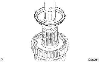 |
Apply gear oil to the No. 1 synchronizer ring set, and install them to the output shaft.
| 16. INSTALL 1ST GEAR |
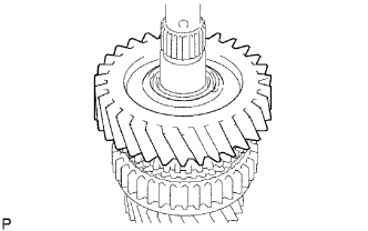 |
Apply gear oil to the 1st gear, and install it to the output shaft.
| 17. INSTALL 1ST GEAR THRUST WASHER |
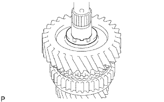 |
Apply gear oil to the thrust washer, and install it to the output shaft.
| 18. INSTALL OUTPUT SHAFT CENTER BEARING |
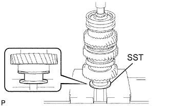 |
Using SST and a press, press in a new center bearing to the output shaft.
- SST
- 09316-60011
(09316-00031)
- NOTICE:
- Install it so that the snap ring groove of the bearing faces to the rear side.
| 19. INSTALL 5TH GEAR |
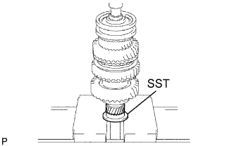 |
Using SST and a press, press in the 5th gear to the output shaft.
- SST
- 09316-60011
(09316-00031)
- NOTICE:
- Check that the 5th gear and the spline of the output shaft fit before installing.
- Face the convex part of the gear to the front side.
- Check that the 5th gear and the spline of the output shaft fit before installing.
| 20. INSPECT 1ST GEAR THRUST CLEARANCE |
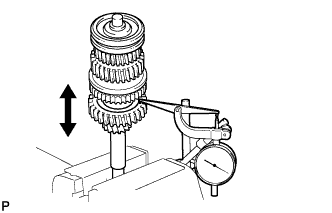 |
Using a dial indicator, measure the thrust clearance.
- Standard clearance:
- 0.20 to 0.45 mm (0.0079 to 0.0177 in.)
| 21. INSPECT 2ND GEAR THRUST CLEARANCE |
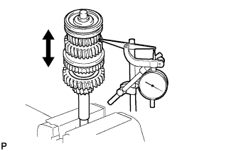 |
Using a dial indicator, measure the thrust clearance.
- Standard clearance:
- 0.10 to 0.25 mm (0.0039 to 0.0098 in.)
| 22. INSPECT 3RD GEAR THRUST CLEARANCE |
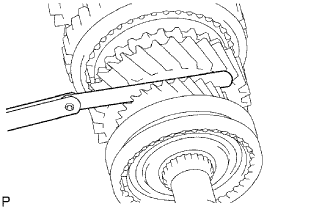 |
Using a feeler gauge, measure the thrust clearance.
- Standard clearance:
- 0.10 to 0.25 mm (0.0039 to 0.0098 in.)
| 23. INSPECT 1ST GEAR RADIAL CLEARANCE |
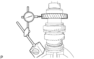 |
Using a dial indicator, measure the radial clearance.
- Standard clearance:
- 0.020 to 0.073 mm (0.0008 to 0.00029 in.)
| 24. INSPECT 2ND GEAR RADIAL CLEARANCE |
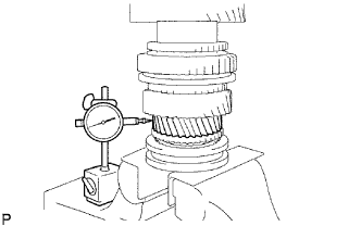 |
Using a dial indicator, measure the radial clearance.
- Standard clearance:
- 0.015 to 0.068 mm (0.0006 to 0.0027 in.)
| 25. INSPECT 3RD GEAR RADIAL CLEARANCE |
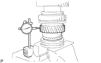 |
Using a dial indicator, measure the radial clearance.
- Standard clearance:
- 0.015 to 0.068 mm (0.0006 to 0.0027 in.)