INSTALLATION
Removal / installation · Vehicles built Jun 2011 – Jul 2012
Versions by build date: Jun 2011 – Jul 2012 Aug 2012 – Jul 2013 from Aug 2013
| 1. CLEAN TURBOCHARGER SUB-ASSEMBLY |
| 2. INSTALL NO. 1 TURBO WATER PIPE SUB-ASSEMBLY |

Install a new gasket and the No. 1 turbo water pipe with the 2 nuts and bolt.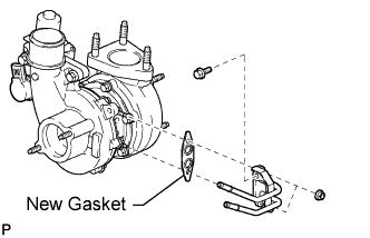

- Torque:
- for bolt:
- 8.0 N*m{ 82 kgf*cm , 71 in.*lbf }
- for nut:
- 12 N*m{ 122 kgf*cm , 9 ft.*lbf }
| 3. INSTALL TURBOCHARGER SUB-ASSEMBLY |
Temporarily install a new gasket and the turbocharger with 3 new nuts.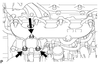
- HINT:
- It is easier to install the turbo oil inlet pipe if the 3 nuts are only loosely installed.
Temporarily install the turbo oil inlet pipe.
- HINT:
- Before installing the oil inlet pipe, clean it.
Install a new gasket and the oil inlet pipe with the 2 nuts, but only loosely install the nuts.
- NOTICE:
- The notch (wide part) of the gasket must face the engine.
Install a new gasket and the oil inlet pipe with the 2 bolts, but only loosely install the bolts.
- NOTICE:
- The claws of the gasket must face the pipe.
Install a new gasket and the oil inlet pipe with the union bolt, but only loosely install the union bolt.
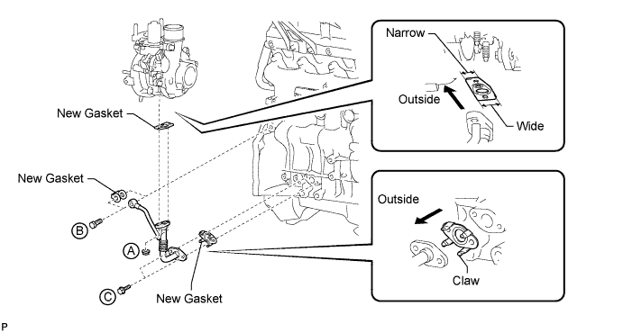
Temporarily install the turbocharger stay with the 2 bolts and nut.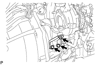
Tighten the 3 nuts of the turbocharger.
- Torque:
- 52 N*m{ 530 kgf*cm , 38 ft.*lbf }
Tighten the 2 nuts labeled A.
- Torque:
- 13 N*m{ 133 kgf*cm , 10 ft.*lbf }
Tighten the union bolt labeled B.
- Torque:
- 26 N*m{ 265 kgf*cm , 19 ft.*lbf }
Tighten the 2 bolts labeled C.
- Torque:
- 12 N*m{ 122 kgf*cm , 9 ft.*lbf }
Tighten the 2 bolts and nut of the turbocharger stay in the order shown in the illustration.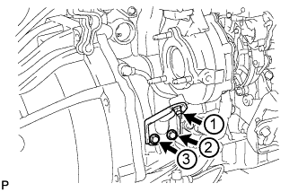
- Torque:
- 38 N*m{ 387 kgf*cm , 28 ft.*lbf }
| 4. INSTALL TURBINE OUTLET ELBOW |
Install a new gasket and the turbine outlet elbow with the 3 nuts.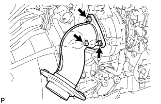
- Torque:
- 26 N*m{ 260 kgf*cm , 19 ft.*lbf }
| 5. INSTALL NO. 1 TURBO WATER HOSE |
Install the 2 No. 1 turbo water hoses.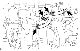
| 6. INSTALL NO. 1 EXHAUST MANIFOLD HEAT INSULATOR |
Temporarily install the No. 1 exhaust manifold heat insulator with the bolt.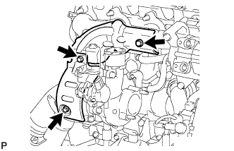
| 7. INSTALL NO. 1 TURBO INSULATOR |
Temporarily install the No. 1 turbo insulator with the 2 bolts.
Tighten the bolt of the No. 1 exhaust manifold heat insulator, and the 2 bolts of the No. 1 turbo insulator.
- Torque:
- 12 N*m{ 122 kgf*cm , 9 ft.*lbf }
| 8. INSTALL COMPRESSOR INLET ELBOW |
Install a new gasket and the compressor inlet elbow with the 2 nuts.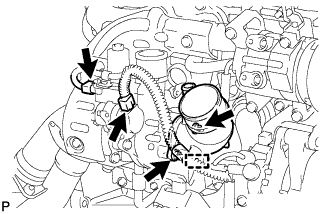
- Torque:
- 19 N*m{ 194 kgf*cm , 14 ft.*lbf }
Connect the 2 connectors and attach the wire harness clamp.
for Ventilation Pipe Type: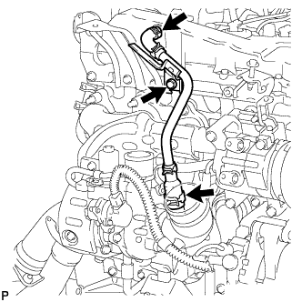
Connect the 2 ventilation hoses and install the ventilation pipe to the cylinder head with the bolt.- Torque:
- 20 N*m{ 204 kgf*cm , 15 ft.*lbf }
| 9. INSTALL INTERCOOLER ASSEMBLY |
Install the intake air connector to the air hoses.
Install the intercooler with the 4 bolts.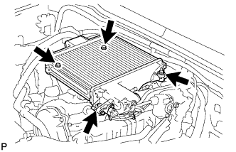
- Torque:
- 12 N*m{ 122 kgf*cm , 9 ft.*lbf }
Install a new No. 2 air hose and then tighten the 2 hose clamps.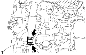
- Torque:
- 6.5 N*m{ 66 kgf*cm , 58 in.*lbf }
Tighten the 2 hose clamps of the No. 1 air hose.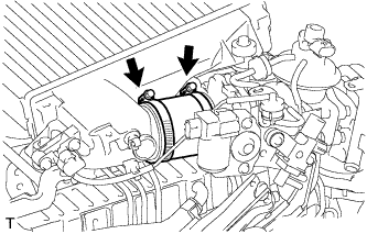
- Torque:
- 6.5 N*m{ 66 kgf*cm , 58 in.*lbf }
Connect the IAT sensor connector and manifold absolute diesel pressure sensor connector.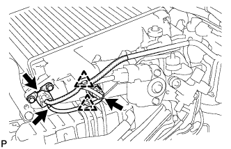
Connect the vacuum hose to the manifold absolute pressure sensor.
Attach the 2 clamps.
| 10. INSTALL NO. 1 ENGINE COVER SUB-ASSEMBLY |
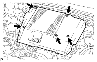 |
Install the engine cover with the 3 bolts and 2 nuts.
- Torque:
- 7.0 N*m{ 71 kgf*cm , 62 in.*lbf }
| 11. INSTALL AIR CLEANER ASSEMBLY |
Connect the air cleaner hose.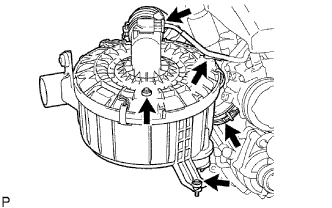
for Ventilation Hose Type:
Connect the ventilation hose.
Install the air cleaner with the 2 bolts.
- Torque:
- 14 N*m{ 143 kgf*cm , 10 ft.*lbf }
Tighten the hose clamp of the compressor inlet elbow.
Connect the MAF meter connector and attach the wire harness clamp.
| 12. INSTALL FRONT EXHAUST PIPE ASSEMBLY |
Using a vernier caliper, measure the free length of the compression spring.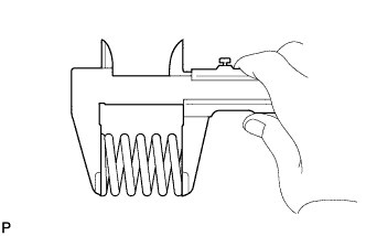
- Minimum length:
- 40 mm (1.57 in.)
Install the front pipe to the pipe support.
Install a new gasket to the outlet pipe.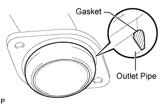
- NOTICE:
- Be careful with the installation direction of the gasket.
- Be careful with the installation direction of the gasket.
- Do not reuse the gasket.
- Do not reuse the gasket.
- To ensure a proper seal, do not use the front pipe to force the gasket onto the outlet pipe.
- To ensure a proper seal, do not use the front pipe to force the gasket onto the outlet pipe.
- HINT:
- Using a plastic-faced hammer, uniformly strike the gasket so that the gasket and outlet pipe are properly fit.
Install the front pipe with the 2 compression springs and 2 bolts. Alternately tighten the bolts in several passes.
- Torque:
- 43 N*m{ 438 kgf*cm , 32 ft.*lbf }
- CAUTION:
- Do not reuse the gasket.
| 13. INSTALL FRONT FENDER SEAL |
Install the front fender seal with the 5 clips.
| 14. INSTALL FRONT FENDER APRON SEAL UPPER |
Install the front fender apron seal upper with the 5 clips.
| 15. INSTALL FRONT WHEEL RH |
| 16. CONNECT CABLE TO NEGATIVE BATTERY TERMINAL |
- NOTICE:
- When disconnecting the cable, some systems need to be initialized after the cable is reconnected (Click here).
| 17. ADD ENGINE COOLANT |
Tighten the radiator drain cock plug by hand.
Tighten the cylinder block drain cock plug.
- Torque:
- 8.0 N*m{ 82 kgf*cm , 71 in.*lbf }
Fill the radiator with TOYOTA Super Long Life Coolant (SLLC) to the reservoir tank's B line.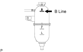
- Standard capacity:
- 9.8 liters (10.4 US qts, 8.6 Imp. qts)
- HINT:
- TOYOTA vehicles are filled with TOYOTA SLLC at the factory. In order to avoid damage to the engine cooling system and other technical problems, only use TOYOTA SLLC or similar high quality ethylene glycol based non-silicate, non-amine, non-nitrite, non-borate coolant with long-life hybrid organic acid technology (coolant with long-life hybrid organic acid technology consists of a combination of low phosphates and organic acids).
- NOTICE:
- Never use water as a substitute for engine coolant.
Press the inlet and outlet radiator hoses several times by hand, and then check the level of the coolant.
If the coolant level drops below the B line, add TOYOTA SLLC to the B line.
Install the radiator reservoir cap.
Using a wrench, install the vent plug.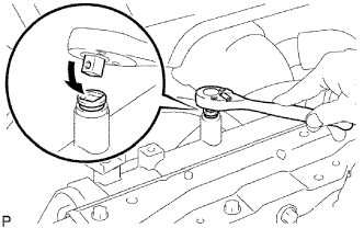
- Torque:
- 2.0 N*m{ 20 kgf*cm , 18 in.*lbf }
Bleed air from the cooling system.
Warm up the engine until the thermostat opens. While the thermostat is open, circulate the coolant for several minutes.
- HINT:
- The thermostat open timing can be confirmed by pressing the inlet radiator hose by hand, and checking when the engine coolant starts to flow inside the hose.
Maintain the engine speed at 2500 to 3000 rpm.
Press the inlet and outlet radiator hoses several times by hand to bleed air.
- CAUTION:
- When pressing the radiator hoses:
- Wear protective gloves.
- Be careful as the radiator hoses are hot.
- Keep your hands away from the radiator fan.
- Wear protective gloves.
Stop the engine and wait until the coolant cools down to ambient temperature.
- CAUTION:
- Do not remove the radiator reservoir cap while the engine and radiator are still hot. Pressurized, hot engine coolant and steam may be released and cause serious burns.
After the coolant cools down, check that the coolant level is at the F line.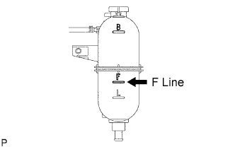
If the coolant level is below the F line, add TOYOTA SLLC to the F line.
| 18. INSPECT FOR ENGINE COOLANT LEAK |
- NOTICE:
- Do not remove the radiator reservoir cap while the engine and radiator are still hot. Pressurized, hot engine coolant and steam may be released and cause serious burns.
Fill the radiator with coolant and attach a radiator cap tester to the radiator reservoir.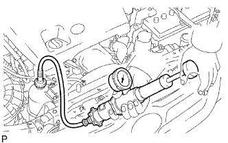
Warm up the engine.
Using the radiator cap tester, increase the pressure inside the radiator to 118 kPa (1.2 kgf/cm2 ,17.1 psi), and check that the pressure does not drop.
If the pressure drops, check the hoses, radiator and water pump for leaks.
If no external leaks are found, check the cylinder block and head.
| 19. INSPECT FOR OIL LEAK |
| 20. INSPECT FOR EXHAUST GAS LEAK |