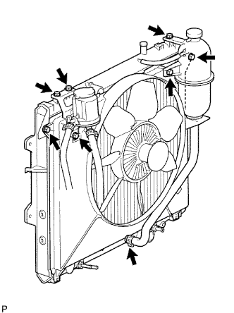
Remove the 4 nuts of the fluid coupling fan, and then remove the shroud together with the coupling fan.
NOTICE:
Be careful not to damage the radiator core.
Remove the fan pulley from the water pump.
6.
DISCONNECT COOLER COMPRESSOR ASSEMBLY (w/ Air Conditioning System)
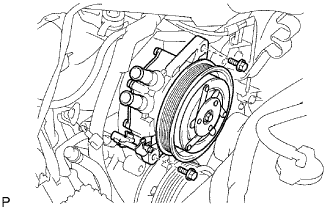
Remove the 4 bolts and disconnect the cooler compressor.
HINT:
It is not necessary to completely remove the compressor. With the hoses connected to the compressor, hang the compressor on the vehicle body with a rope.
7.
REMOVE VISCOUS WITH MAGNET CLUTCH HEATER ASSEMBLY (for Cold Area Specification Vehicles)
Disconnect the connector.
Remove the 2 bolts and viscous with magnet clutch heater assembly.
8.
REMOVE GENERATOR ASSEMBLY
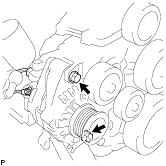
Remove the nut and generator wire.
Disconnect the generator connector.
Remove the 2 bolts and generator.
9.
REMOVE V-RIBBED BELT TENSIONER ASSEMBLY
Remove the 4 bolts and tensioner.
10.
REMOVE NO. 2 AIR CLEANER PIPE SUB-ASSEMBLY
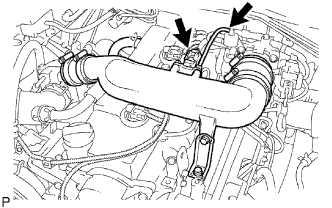
Disconnect the manifold absolute pressure sensor connector.
Disconnect the vacuum hose from the gas filter.
Loosen the 2 clamps of the No. 1 and No. 2 air hoses.
Remove the bolt and cleaner pipe together with the 2 air hoses.
11.
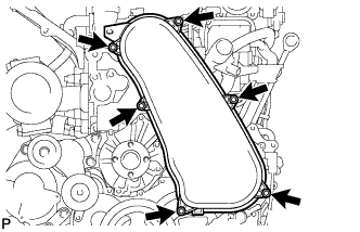
REMOVE NO. 1 TIMING BELT COVER
Remove the bolt and water hose clamp.
Remove the wire harness clamp.
Remove the 6 bolts and timing belt cover.
12.
REMOVE TIMING BELT
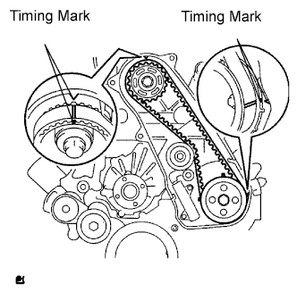
Turn the crankshaft clockwise and align the timing marks as shown in the illustration.
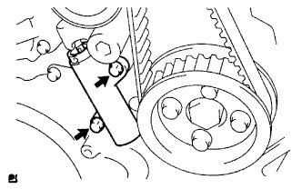
Uniformly loosen the 2 bolts and remove the timing belt tensioner.
Remove the timing belt.
Using a 10 mm hexagon wrench, remove the bolt, timing belt idler and washer.
HINT:
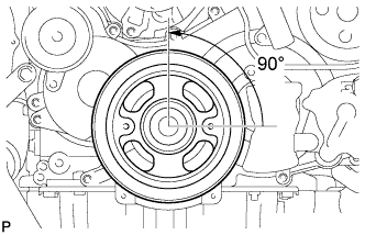
When turning the camshaft while the timing belt is removed, turn the crankshaft 90° counterclockwise.
When installing the timing belt, return the camshaft to the timing marks and then turn the crankshaft clockwise until it aligns with the timing marks, as shown in the illustration.
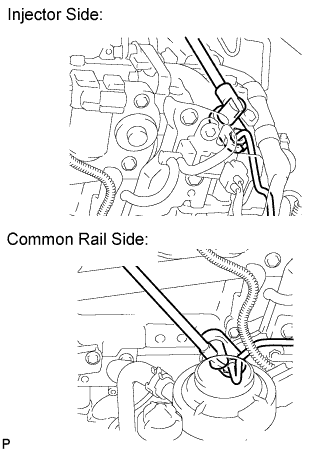
After removing the fuel pipe, cover the outlets on the common rail with tape to keep out foreign matter.
After removing the fuel pipe, put it in a plastic bag to prevent foreign matter from contaminating its injector inlet.
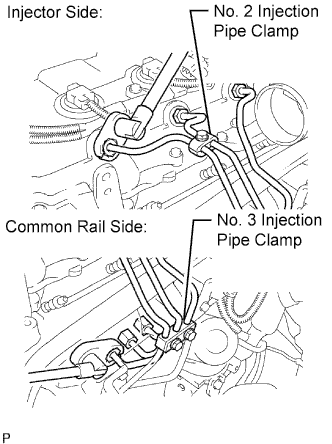
Remove the bolt and No. 2 injection pipe clamp.
Remove the 2 nuts and No. 3 injection pipe clamp.
Using a 17 mm union nut wrench, loosen the union nuts and remove the No. 1, No. 2 and No. 3 injection pipes.
14.
REMOVE NO. 4 INJECTION PIPE SUB-ASSEMBLY
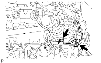
Remove the 2 bolts.
NOTICE:
If an injection pipe clamp is removed from the No. 4 injection pipe, replace the injection clamp with a new one.
Using a 17 mm union nut wrench, loosen the union nuts and remove the No. 4 injection pipe.
15.
REMOVE CYLINDER HEAD COVER SUB-ASSEMBLY
NOTICE:
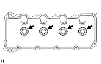
If the cylinder head cover is removed, replace the 4 No. 3 cylinder head cover gaskets with new ones.
Disconnect the ventilation hose.
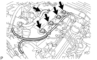
Disconnect the 4 injector connectors.
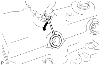
Using a small screwdriver, remove the 4 nozzle holder seals by prying the portion between each nozzle holder seal and the cutout part of the cylinder head cover.
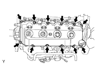
Remove the 10 bolts, 2 nuts, cylinder head cover and gasket.
Remove the 4 No. 3 cylinder head cover gaskets from the cylinder head cover.
16.
REMOVE CAMSHAFT TIMING PULLEY
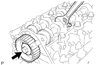
Remove the bolt of the camshaft timing pulley by holding the camshaft with a wrench.
NOTICE:
Make sure to remove the bolt of the camshaft timing pulley with the timing belt not installed.
Remove the camshaft timing pulley.
17.
REMOVE NO. 2 TIMING BELT COVER
Remove the 4 bolts, nut and timing belt cover.
18.
REMOVE WATER PUMP ASSEMBLY
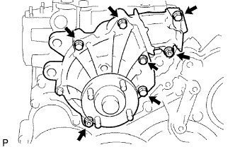
Remove the 2 nuts, 5 bolts, water pump and gasket.