REASSEMBLY
Removal / installation · Vehicles built from Jun 2011
| 1.
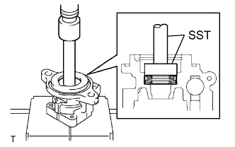
INSTALL VANE PUMP HOUSING OIL SEAL |
 |
Using SST and a press, install a new oil seal.
- SST
- 09950-60010
09950-70010
(09951-00400, 09951-07150)
- NOTICE:
- Make sure to install the oil seal facing the correct direction.
- Be sure not to damage the oil seal.
| 2.
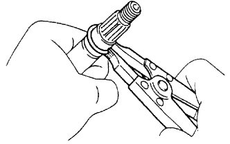
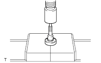
INSTALL VANE PUMP SHAFT BEARING |
|
Using a snap ring expander, install a new snap ring.
- NOTICE:
- Do not damage the shaft.
- Using a press, press the shaft into the bearing.
- NOTICE:
- Make sure to install the shaft facing the correct direction.
- Be sure not to damage the bearing.
| 3.
INSTALL VANE PUMP SHAFT WITH BEARING |
|
Using a press, press the shaft (with bearing) into the vane pump gear.
| 4.
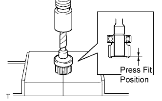
INSTALL VANE PUMP GEAR |
|
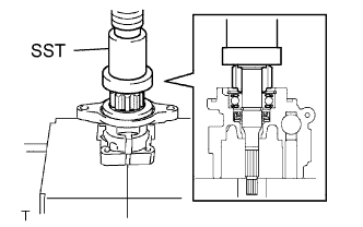
Using SST and a press, press the shaft (with bearing and gear) into the front housing.
- SST
- 09950-60010
09950-70010
(09951-00420, 09951-07150)
| 5.
INSTALL FRONT VANE PUMP SIDE PLATE |
|
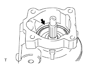
Coat a new O-ring with power steering fluid.
Install the O-ring to the front housing.
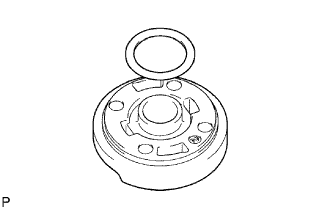
- Coat a new O-ring with power steering fluid.
Install the O-ring to the front side plate.
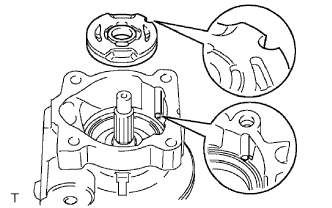
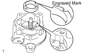
- Install side plate front to the front housing while aligning the semicircle-shaped cuts of both parts.
- NOTICE:
- Be sure to install the plate in the correct position and direction.
| 6.
INSTALL VANE PUMP CAM RING |
|
With the engraved mark facing upward, install the cam ring to the housing while aligning the semicircle-shaped cuts of both parts.
- NOTICE:
- Be sure to install the ring in the correct position and direction.
| 7.
INSTALL VANE PUMP ROTOR |
|
Install the vane pump rotor.
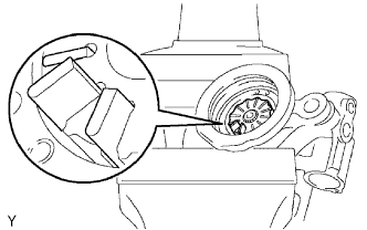
Install the 10 vane pump plates with the round ends facing outward.
| 8.
INSTALL REAR VANE PUMP HOUSING |
|
Coat a new O-ring with power steering fluid and install it onto the rear housing.
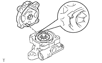
Align the straight pin of the rear housing with the hole created by the semicircle-shaped cuts of the cam ring, front side plate and front housing.
- NOTICE:
- Make sure that the O-ring is not out of position before installing the rear vane pump housing.
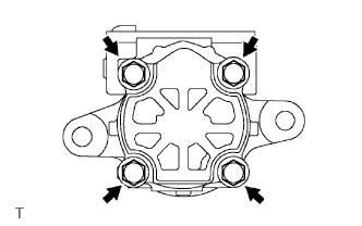
- Install the rear housing with the 4 bolts.
-
Torque:
- 22 N*m{
224 kgf*cm
, 16 ft.*lbf
}
| 9.
INSPECT PRELOAD |
|
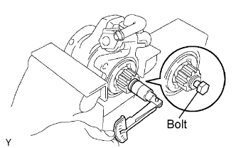
Check that the pump rotates smoothly without abnormal noise.
Temporarily install a bolt to the vane pump shaft.
Using a bolt and 10 mm socket wrench, check the power steering vane pump rotating torque.
Bolt part No.: 91111-51035
- Rotating torque:
- 0.27 N*m (2.8 kgf*cm, 2.4 in.*lbf) or less
| 10.
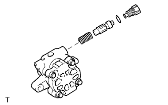
INSTALL FLOW CONTROL VALVE |
|
Install the spring.
Install the flow control valve facing in the correct direction.
Coat a new O-ring with power steering fluid and install it to the pressure port union.
Install the pressure port union.
-
Torque:
- 69 N*m{
704 kgf*cm
, 51 ft.*lbf
}
| 11.
INSTALL POWER STEERING SUCTION PORT UNION |
|
Coat a new O-ring with power steering fluid and install it to the suction port union.
Install the suction port union with the 2 bolts.
-
Torque:
- 12 N*m{
122 kgf*cm
, 9 ft.*lbf
}