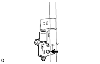
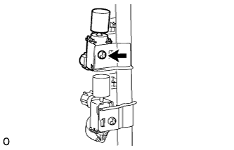
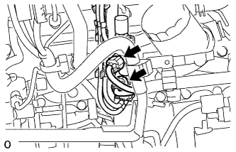
Install the No. 1 VSV to the manifold stay with the screw.
Torque:
3.5 N*m{
36 kgf*cm
, 31 in.*lbf
}
3.
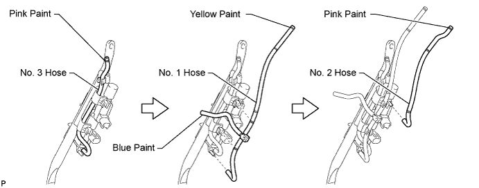
CONNECT NO. 3 VACUUM TRANSMITTING HOSE
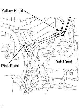
Connect the vacuum hose to the VSV (for No. 2 EGR valve) shown in the illustration below.
4.
CONNECT NO. 1 VACUUM TRANSMITTING HOSE
Connect the vacuum hose to the VSV (for E-VRV) shown in the illustration below.
5.
CONNECT NO. 2 VACUUM TRANSMITTING HOSE
Connect the vacuum hose to the VSV (for electric EGR control valve) shown in the illustration below.
6.
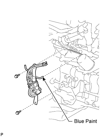
INSTALL MANIFOLD STAY WITH VACUUM SWITCHING VALVE
Install the manifold stay with VSV with the 2 bolts, and connect the No. 1 vacuum transmitting hose (color is "Blue") to the No. 2 vacuum transmitting pipe.
Torque:
19 N*m{
194 kgf*cm
, 14 ft.*lbf
}
NOTICE:
Install the vacuum hoses' color matches the connection areas' color.
Connect the 3 vacuum hoses.
NOTICE:
Install the vacuum hoses' color matches the connection areas' color.
Make sure the vacuum hoses' color matches the connection areas' color.