2014 Hilux · Service Manual ENGINE

REMOVAL

Removal / installation · Vehicles built Jun 2011 – Jul 2012

Versions by build date: Jun 2011 – Jul 2012 Aug 2012 – Jul 2013 from Aug 2013

NOTICE:
  1. When replacing the injectors (including shuffling the injectors between the cylinders), common rail or cylinder head, it is necessary to replace the injection pipes with new ones.
  2. When replacing the fuel supply pump, common rail, cylinder block, cylinder head, cylinder head gasket or timing gear case, it is necessary to replace the fuel inlet pipe with a new one.
  3. After removing the injection pipes and fuel inlet pipe, clean them with a brush and compressed air.


1. DISCONNECT CABLE FROM NEGATIVE BATTERY TERMINAL

CAUTION:
Wait at least 90 seconds after disconnecting the cable from the negative (-) battery terminal to prevent airbag activation.

NOTICE:
When disconnecting the cable, systems need to be initialized after the cable is reconnected (Click here).


2. REMOVE NO. 1 ENGINE UNDER COVER
  1. Remove the 4 bolts and No. 1 engine under cover.


3. REMOVE NO. 2 ENGINE UNDER COVER
  1. Remove the 2 bolts and No. 2 engine under cover.


4. DRAIN ENGINE OIL
  1. Remove the oil filter cap.

  1. Remove the oil drain plug, and drain the engine oil from the oil pan.

    NOTICE:
    Collect the oil in an oil disposal container.


5. REMOVE INTERCOOLER ASSEMBLY
  1. Remove the intercooler assembly (Click here).


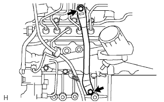
6. REMOVE MANIFOLD STAY

A099622E01
  1. Remove the 2 bolts and stay.


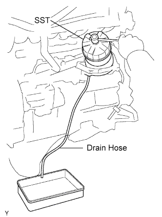
7. REMOVE OIL FILTER SUB-ASSEMBLY

B011502E01
  1. Using SST, remove the oil filter.

    SST
    09228-07501  

    HINT:
    Insert the drain hose in the oil filter. Put the drain oil container beneath the drain hose to collect the oil from the oil filter.


8. REMOVE NO. 1, NO. 2 AND NO. 3 INJECTION PIPE SUB-ASSEMBLY

NOTICE:
  1. After removing the fuel pipe, cover the outlets on the common rail with tape to keep out foreign matter.
  2. After removing the fuel pipe, put it in a plastic bag to prevent foreign matter from contaminating its injector inlet.

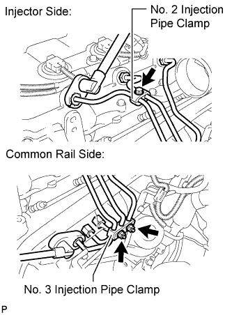
  1. A231803E01
    Remove the bolt and No. 2 injection pipe clamp.

  1. Remove the 2 nuts and No. 3 injection pipe clamp.

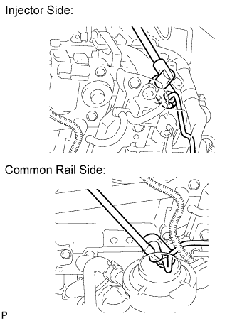
  1. Using a 17 mm union nut wrench, loosen the union nuts and remove the No. 1, No. 2 and No. 3 injection pipes.


9. REMOVE NO. 4 INJECTION PIPE SUB-ASSEMBLY

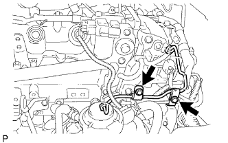
  1. A098893E01
    Remove the 2 bolts and disconnect the 2 injection pipe clamps.

    NOTICE:
    If an injection pipe clamp is removed from the No. 4 injection pipe, replace the injection clamp with a new one.

  1. A231804E01
    Using a 17 mm union nut wrench, loosen the union nuts and remove the No. 4 injection pipe.


10. REMOVE NO. 2 NOZZLE LEAKAGE PIPE ASSEMBLY
  1. Disconnect the 3 fuel hoses.

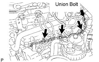
  1. A098898E05
    Remove the union bolt, 3 bolts, No. 2 nozzle leakage pipe and gasket.


11. REMOVE FUEL INLET PIPE SUB-ASSEMBLY
  1. Remove the engine oil level dipstick.

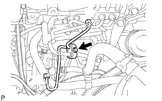
  1. G036615E01
    Remove the bolt and clamp.

  1. Remove the bolt and engine oil level dipstick guide.

  1. Remove the O-ring engine oil level dipstick guide.

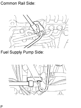
  1. A098969E03
    Using a 17 mm union nut wrench, loosen the union nuts and remove the fuel inlet pipe.


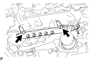
12. REMOVE COMMON RAIL ASSEMBLY
  1. Disconnect the 2 connectors.

  1. A231856
    Remove the 2 bolts, common rail and No. 2 intake manifold insulator.

    NOTICE:
    Do not remove the pressure discharge valve and fuel pressure sensor.

← COMPONENTS (from Jun 2011)REMOVAL (Aug 2012 – Jul 2013) →