REMOVAL
Removal / installation · Vehicles built from Jun 2011
- NOTICE:
- When replacing the common rail, also replace the injection pipe.
- After removing the injection pipes and fuel inlet pipe, clean them with a brush and compressed air.
- When replacing the common rail, also replace the injection pipe.
| 1. DISCONNECT CABLE FROM NEGATIVE BATTERY TERMINAL |

- CAUTION:
- Wait at least 90 seconds after disconnecting the cable from the negative (-) battery terminal to prevent airbag and seat belt pretensioner activation.
| 2. REMOVE NO. 1 ENGINE UNDER COVER (for 4WD) |
Remove the 4 bolts and under cover.
| 3. REMOVE NO. 2 ENGINE UNDER COVER (for 4WD) |
Remove the 4 bolts and under cover.
| 4. DRAIN ENGINE OIL |
| 5. LOOSEN FUEL TANK CAP ASSEMBLY |
| 6. DRAIN FUEL |
| 7. REMOVE INTERCOOLER ASSEMBLY |
Remove the intercooler assembly (Click here).
| 8. REMOVE MANIFOLD STAY |
Disconnect the 3 vacuum hoses from the 2 VSV.
Remove the 2 bolts and stay.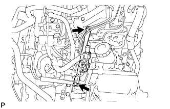

| 9. REMOVE OIL FILTER SUB-ASSEMBLY |
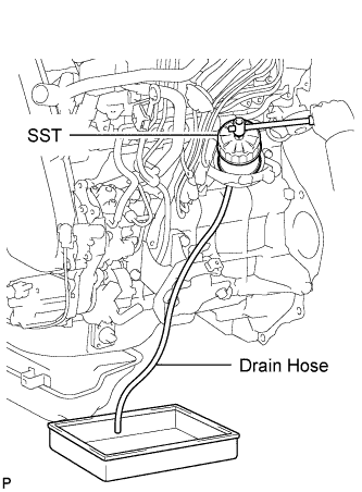 |
Using SST, remove the oil filter.
- SST
- 09228-07501
- HINT:
- Insert the drain hose in the oil cooler cover. Put the disposal container beneath the drain hose to collect the oil from the oil filter cover.
| 10. REMOVE NO. 1, NO. 2 AND NO. 3 INJECTION PIPE |
- NOTICE:
- After removing the fuel pipe, cover the outlets on the common rail with tape to keep out foreign matter.
- After removing the fuel pipe, put it in a plastic bag to prevent foreign matter from contaminating its injector inlet.
- After removing the fuel pipe, cover the outlets on the common rail with tape to keep out foreign matter.
Remove the 2 nuts and No. 3 injection pipe clamp.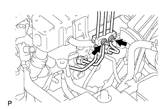
Remove the 2 bolts and 2 No. 2 injection pipe clamps.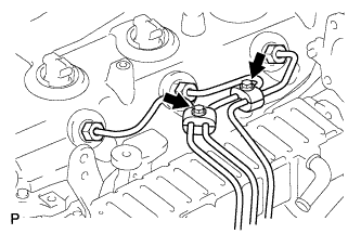
Using a 17 mm union nut wrench, loosen the union nuts and remove the No. 1, No. 2 and No. 3 injection pipes.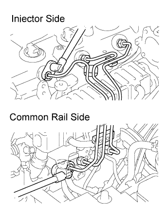
| 11. REMOVE EGR COOLER ASSEMBLY |
Remove the EGR cooler assembly (Click here).
| 12. REMOVE NO. 4 INJECTION PIPE |
Remove the bolt and disconnect the injection pipe clamp.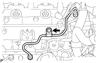
Using a 17 mm union nut wrench, loosen the union nuts and remove the No. 4 injection pipe.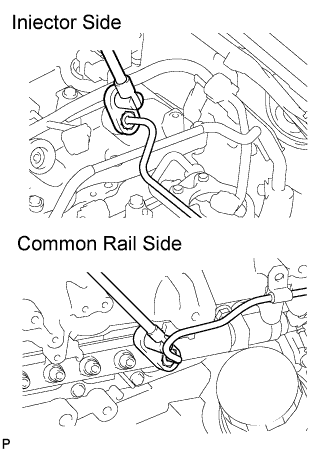
| 13. REMOVE NO. 2 NOZZLE LEAKAGE PIPE ASSEMBLY |
Disconnect the 3 fuel hoses.
Remove the check valve, 3 bolts, leakage pipe and gasket.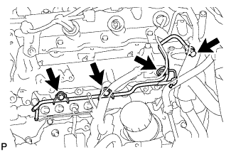
| 14. REMOVE FUEL INLET PIPE SUB-ASSEMBLY |
Remove the bolt and clamp.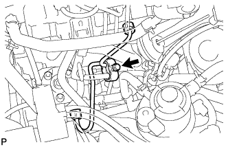
Remove the bolt and oil level gauge guide.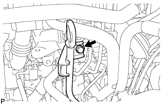
Using a 17 mm union nut wrench, loosen the union nuts and remove the fuel inlet pipe.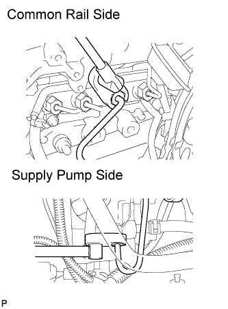
| 15. REMOVE COMMON RAIL ASSEMBLY |
Disconnect the 2 connectors.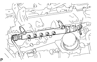
Remove the 2 bolts, common rail and insulator.
- NOTICE:
- Do not remove the pressure discharge valve and pressure sensor.