2014 Hilux · Service Manual ENGINE

REMOVAL

Removal / installation · Vehicles built Aug 2012 – Jul 2013

Versions by build date: Jun 2011 – Jul 2012 Aug 2012 – Jul 2013 from Aug 2013

NOTICE:
  1. When replacing the injectors (including shuffling the injectors between the cylinders), common rail or cylinder head, it is necessary to replace the injection pipes with new ones.
  2. When replacing the fuel supply pump, common rail, cylinder block, cylinder head, cylinder head gasket or timing gear case, it is necessary to replace the fuel inlet pipe with a new one.
  3. After removing the injection pipes and fuel inlet pipe, clean them with a brush and compressed air.


1. DISCONNECT CABLE FROM NEGATIVE BATTERY TERMINAL

NOTICE:
When disconnecting the cable, some systems need to be initialized after the cable is reconnected (Click here).


2. REMOVE ELECTRIC EGR CONTROL VALVE ASSEMBLY WITH NO. 2 EGR VALVE AND EGR COOLER
(Click here)

3. REMOVE NO. 4 INJECTION PIPE SUB-ASSEMBLY

  1. A252273
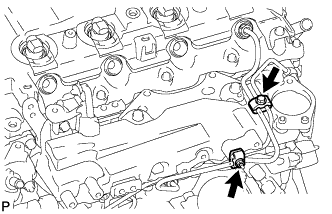
    Remove the bolt, nut and 2 No. 2 injection pipe clamps.

  1. A252274
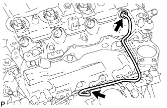
    Using a 17 mm union nut wrench, loosen the union nuts and remove the No. 4 injection pipe.


4. REMOVE WIRING HARNESS CLAMP BRACKET

  1. A252275E01
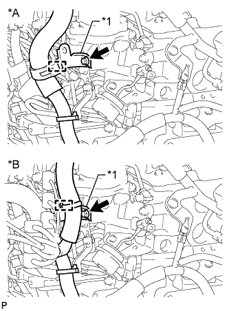
    Detach the wire harness clamp.
    Text in Illustration 
    *A
    for LHD
    *B
    for RHD
    *1
    Wiring Harness Clamp Bracket

  1. Remove the bolt and wiring harness clamp bracket.


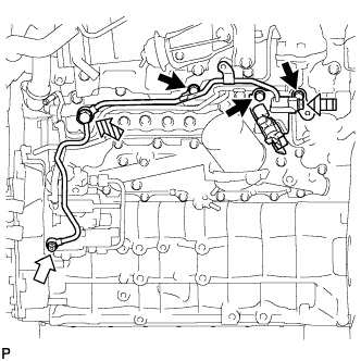
5. REMOVE NO. 2 FUEL PIPE

  1. A252276
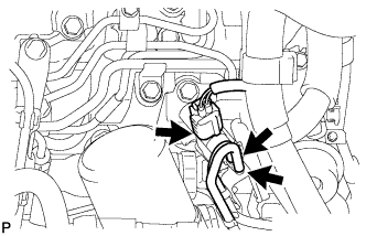
    Disconnect the vacuum switching valve connector and 2 vacuum transmitting hoses.

  1. A252278
    Using a 6 mm hexagon wrench, remove the supply pump hollow screw and gasket.
    Text in Illustration 
    V100135
    Bolt
    V100136
    Supply Pump Hollow Screw
    V100137
    Fuel Check Valve
    V100138
    Union Bolt

  1. Remove the fuel check valve, union bolt and 2 gaskets.

  1. Remove the 3 bolts and No. 2 fuel pipe.


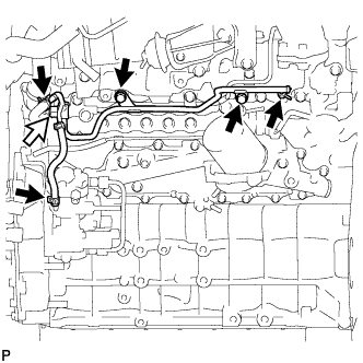
6. REMOVE NO. 3 NOZZLE LEAKAGE PIPE

  1. A252280
    Disconnect the 3 fuel hoses.
    Text in Illustration 
    V100136
    Fuel Check Valve

  1. Remove the 2 bolts.

  1. Remove the fuel check valve, gasket and No. 3 nozzle leakage pipe.


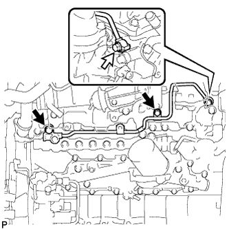
7. REMOVE NO. 2 NOZZLE LEAKAGE PIPE ASSEMBLY

  1. A252281
    Remove the 2 bolts.
    Text in Illustration 
    V100136
    Union Bolt

  1. Remove the union bolt, gasket and No. 2 nozzle leakage pipe.


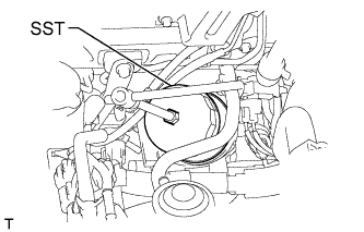
8. REMOVE OIL FILTER SUB-ASSEMBLY

  1. A227248E01
    Using SST, remove the oil filter.
    SST
    09228-07501  

    HINT:
    Insert the drain hose in the oil filter. Put the disposal container beneath the drain hose to collect the oil from the oil filter.


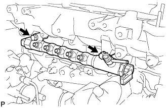
9. REMOVE COMMON RAIL ASSEMBLY
  1. Disconnect the pressure discharge valve connector.

  1. A239630
    Remove the 2 bolts and common rail.

    NOTICE:
    Do not remove the pressure discharge valve or fuel pressure sensor.

← REMOVAL (Jun 2011 – Jul 2012)REMOVAL (from Aug 2013) →