INSTALLATION
Removal / installation · Vehicles built from Jun 2011
| 1. INSTALL CONVERTER PROTECTOR STAY |

Install the 2 No. 1 converter protector stays and 2 No. 2 converter protector stays to the front exhaust pipe.
| 2. INSTALL MONOLITHIC CONVERTER PROTECTOR |
Install the upper monolithic converter protector and lower monolithic converter protector with the 4 bolts and 4 nuts.
- Torque:
- 11 N*m{ 107 kgf*cm , 8 ft.*lbf }
| 3. INSTALL EXHAUST PIPE CLAMP SUB-ASSEMBLY |
Install the exhaust pipe clamp with the bolt and a new nut.
- Torque:
- 18 N*m{ 184 kgf*cm , 13 ft.*lbf }
| 4. INSTALL NO. 3 EXHAUST GAS TEMPERATURE SENSOR |
- NOTICE:
- If the sensor is dropped, replace it with a new one.
Using a 14 mm union nut wrench, install the No. 3 exhaust gas temperature sensor.
- Torque:
- 30 N*m{ 306 kgf*cm , 22 ft.*lbf }
- NOTICE:
- Use the formula to calculate special torque values for situations where a union nut wrench is combined with a torque wrench (Click here).
| 5. INSTALL WIRING HARNESS CLAMP BRACKET |
Install the wiring harness clamp bracket with the bolt.
- Torque:
- 21 N*m{ 214 kgf*cm , 15 ft.*lbf }
| 6. INSTALL NO. 2 EXHAUST GAS TEMPERATURE SENSOR |
- NOTICE:
- If the sensor is dropped, replace it with a new one.
Using a 14 mm union nut wrench, install the No. 2 exhaust gas temperature sensor.
- Torque:
- 30 N*m{ 306 kgf*cm , 22 ft.*lbf }
- NOTICE:
- Use the formula to calculate special torque values for situations where a union nut wrench is combined with a torque wrench (Click here).
Attach the 5 clamps.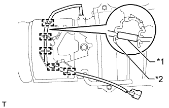

Text in Illustration *1
Wire Harness
*2
Clamp
- HINT:
- Make sure that the part of the wire harness is as shown in the illustration.
| 7. INSTALL EXHAUST GAS TEMPERATURE SENSOR |
- NOTICE:
- If the sensor is dropped, replace it with a new one.
Using a 14 mm union nut wrench, install the exhaust gas temperature sensor.
- Torque:
- 30 N*m{ 306 kgf*cm , 22 ft.*lbf }
- NOTICE:
- Use the formula to calculate special torque values for situations where a union nut wrench is combined with a torque wrench (Click here).
- HINT:
-
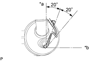
- The sensor should be assembled within 20° of the prescribed position on either side.
Text in Illustration *a
Top
*b
LH
| 8. INSTALL FRONT EXHAUST PIPE ASSEMBLY |
Using a vernier caliper, measure the free length of the compression spring.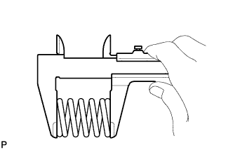
- Minimum free length:
- 43 mm (1.69 in.)
- If the free length is less than the minimum, replace the compression spring.
Using a plastic-faced hammer and wooden block, tap on a new gasket until its surface is flush with the front exhaust pipe.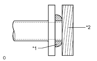
Text in Illustration *1
Gasket
*2
Wooden Block
- NOTICE:
- Be sure to install the gasket so that it faces the correct direction.
- Do not reuse the gasket.
- Do not damage the gasket.
- When connecting the exhaust pipe, do not push in the gasket with the exhaust pipe.
- Be sure to install the gasket so that it faces the correct direction.
Install a new gasket and the front exhaust pipe to the No. 2 turbine outlet elbow with 3 new nuts.
- Torque:
- 54 N*m{ 554 kgf*cm , 40 ft.*lbf }
Connect the front exhaust pipe to the 2 exhaust pipe supports.
Connect the No. 6 exhaust pipe air hose and No. 7 exhaust pipe air hose to the front exhaust pipe with 2 new clips.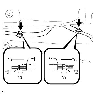
Text in Illustration *1
Clip
*2
Stopper
*a
4 to 10 mm (0.157 to 0.394 in.)
*b
Pink Paint
*c
Blue Paint

Paint Mark
- NOTICE:
- Align the paint marks of the front exhaust pipe and exhaust pipe air hose and push on the exhaust pipe air hose until it contacts the stopper.
- Make sure the clip is 4 to 10 mm (0.157 to 0.394 in.) from the end of the exhaust pipe air hose when installing the clip.
- Make sure that there is no slack in the exhaust pipe air hose, and that it is not twisted or bent.
- Take care not to damage the inner or outer surface of the exhaust pipe air hose when installing it. If the exhaust pipe air hose is damaged, replace it with a new one.
- Align the paint marks of the front exhaust pipe and exhaust pipe air hose and push on the exhaust pipe air hose until it contacts the stopper.
Connect the No. 3 exhaust gas temperature sensor connector and attach the clamp.
Connect the No. 2 exhaust gas temperature sensor connector and attach the clamp.
Connect the exhaust gas temperature sensor connector and attach the clamp.
| 9. INSTALL AIR FUEL RATIO SENSOR |
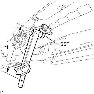 |
Using SST, install the air fuel ratio sensor to the front exhaust pipe.
- SST
- 09224-00010
- Torque:
- without SST:
- 44 N*m{ 449 kgf*cm , 32 ft.*lbf }
- with SST:
- 40 N*m{ 408 kgf*cm , 30 ft.*lbf }
Text in Illustration *1
Fulcrum Length
- HINT:
- Use a torque wrench with a fulcrum length of 30 cm (11.8 in.). When using a torque wrench with a fulcrum length that is not 30 cm (11.8 in.), calculate the torque specification for the torque wrench and SST based on the "without SST" torque specification (Click here).
- Make sure SST and the wrench are connected in a straight line.
- Use a torque wrench with a fulcrum length of 30 cm (11.8 in.). When using a torque wrench with a fulcrum length that is not 30 cm (11.8 in.), calculate the torque specification for the torque wrench and SST based on the "without SST" torque specification (Click here).
Connect the air fuel ratio sensor connector.
| 10. INSTALL NO. 2 EXHAUST PIPE SUPPORT BRACKET |
Install the No. 2 exhaust pipe support bracket with the 2 bolts.
- Torque:
- 19 N*m{ 194 kgf*cm , 14 ft.*lbf }
| 11. INSTALL NO. 3 FRAME CROSSMEMBER SUB-ASSEMBLY (for Manual Transmission) |
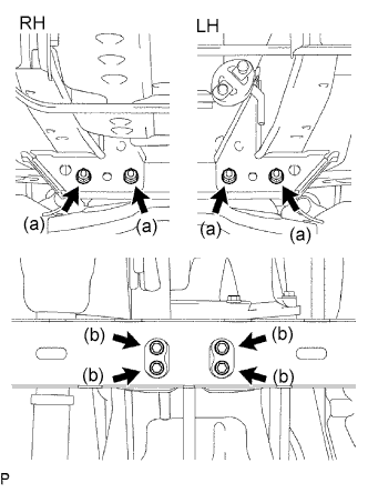 |
Install the frame crossmember with the 4 bolts and 4 nuts.
- Torque:
- 50 N*m{ 510 kgf*cm , 37 ft.*lbf }
Install the 4 set bolts to the No. 1 engine mounting insulator rear.
- Torque:
- 17 N*m{ 173 kgf*cm , 13 ft.*lbf }
| 12. INSTALL NO. 3 FRAME CROSSMEMBER SUB-ASSEMBLY (for Automatic Transmission) |
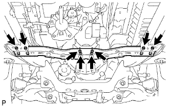 |
Install the frame crossmember to the engine mounting insulator with the 4 set bolts.
- Torque:
- 17 N*m{ 173 kgf*cm , 13 ft.*lbf }
Connect the ends of the frame crossmember to the vehicle with the 4 bolts and 4 nuts.
- Torque:
- 50 N*m{ 510 kgf*cm , 37 ft.*lbf }
| 13. INSTALL NO. 2 ENGINE UNDER COVER |
- Torque:
- 28 N*m{ 286 kgf*cm , 21 ft.*lbf }
| 14. INSTALL CENTER EXHAUST PIPE ASSEMBLY |
Install the center exhaust pipe to the 3 exhaust pipe supports.
Install the center exhaust pipe and 2 compression springs with the 2 bolts.
- Torque:
- 43 N*m{ 438 kgf*cm , 32 ft.*lbf }
| 15. INSTALL TAILPIPE ASSEMBLY |
Install the tailpipe to the exhaust pipe support.
Install a new gasket and connect the tailpipe to the center exhaust pipe with the 2 bolts and 2 nuts. Alternately tighten the bolts in several passes.
- Torque:
- 48 N*m{ 489 kgf*cm , 35 ft.*lbf }
- NOTICE:
- Do not reuse the gasket.
| 16. INSPECT FOR EXHAUST GAS LEAK |
- If gas is leaking, tighten the areas necessary to stop the leak. Replace damaged parts as necessary.