2TR-FE ENGINE CONTROL CRANKSHAFT POSITION SENSOR INSTALLATION
PROCEDURE

 1.INSTALL CRANKSHAFT POSITION SENSOR
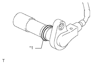
| *1 | O-Ring |
Apply a light coat of engine oil to the O-ring of the crankshaft position sensor.
Install the crankshaft position sensor with the bolt.
- Torque:
- 8.5 N*m (87 kgf*cm, 75 in.*lbf)
- NOTICE:
-
Make sure that the O-ring is not cracked or jammed when installing the sensor.
Connect the crankshaft position sensor connector to the connector bracket.
Attach the harness clamp.
Connect the crankshaft position sensor connector.
2.INSTALL NO. 1 COMPRESSOR MOUNTING BRACKET (w/ Air Conditioning System)
3.CONNECT COOLER COMPRESSOR ASSEMBLY (w/ Air Conditioning System)
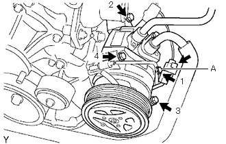
Temporarily install the cooler compressor with the bolt labeled A.
Install the remaining 3 bolts, and then tighten the 4 bolts in the order shown in the illustration.
- Torque:
- 25 N*m (255 kgf*cm, 18 ft.*lbf)
- NOTICE:
-
In order to prevent misalignment, which causes belt rattle, tightening of the bolts must be performed in the order shown.
Connect the cooler compressor connector.
Connect the suction hose sub-assembly with the bolt.
- Torque:
- 5.4 N*m (55 kgf*cm, 48 in.*lbf)
4.INSTALL FAN AND GENERATOR V BELT