Home › Engine / Hybrid System › 1KD-FTV ENGINE CONTROL › ECD SYSTEM(w/o EGR Cooler) › 2011.10–2012.04
RM1840EF _51 Engine / Hybrid System _009570 1KD-FTV ENGINE CONTROL _0052103 ECD SYSTEM(w/o EGR Cooler) J

1KD-FTV ENGINE CONTROL  ECD SYSTEM(w/o EGR Cooler)  VC Output Circuit  


DESCRIPTION

The VC voltage (5 V) is generated in the ECM. The voltage is used to supply power to the throttle body assembly, turbo pressure sensor, accelerator position sensor and fuel pressure sensor.

WIRING DIAGRAM
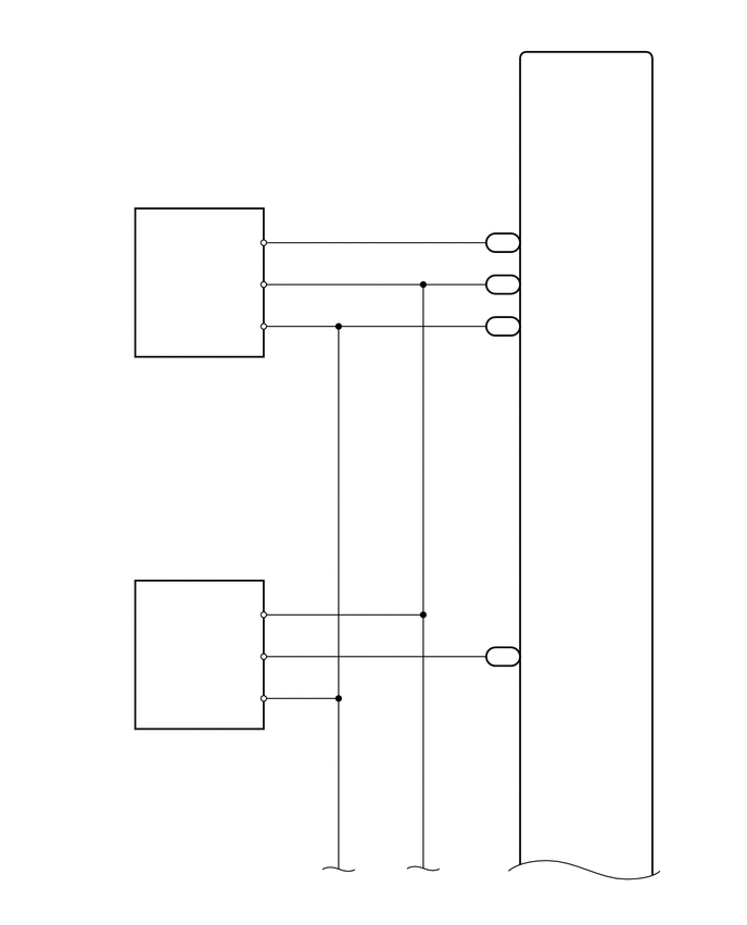
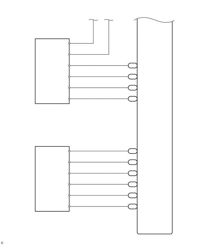
A303421
5.448,0.25 5.906,0.448 0.458,0.198 10 false ECM 2.167,2.26 2.542,2.469 0.375,0.208 10 false VTA 2.25,2.635 2.563,2.833 0.313,0.198 10 false VC 2.271,3.052 2.563,3.25 0.292,0.198 10 false E2 2.615,2.146 3.073,2.344 0.458,0.198 10 false 3 2.615,2.531 3.073,2.729 0.458,0.198 10 false 1 2.625,2.938 3.083,3.135 0.458,0.198 10 false 2 4.698,2.24 5.021,2.427 0.323,0.188 10 false C23 4.698,2.646 5.021,2.833 0.323,0.188 10 false C22 4.708,3.042 5.031,3.229 0.323,0.188 10 false C22 4.75,2.052 4.99,2.229 0.24,0.177 10 false 29 4.75,2.469 4.99,2.646 0.24,0.177 10 false 18 4.75,2.865 4.99,3.042 0.24,0.177 10 false 28 5.083,2.25 5.542,2.448 0.458,0.198 10 false VLU 5.094,2.646 5.552,2.844 0.458,0.198 10 false VC 5.083,3.063 5.542,3.26 0.458,0.198 10 false E2 1.208,3.625 3.031,3.896 1.823,0.271 10 false Throttle Body Assembly 1.188,3.448 1.646,3.646 0.458,0.198 10 false C9 0.917,7.042 1.375,7.24 0.458,0.198 10 false C20 0.906,7.208 3.188,7.448 2.281,0.24 10 false Manifold Absolute Pressure Sensor 2.271,5.823 2.563,6 0.292,0.177 10 false VC 2.25,6.208 2.563,6.438 0.313,0.229 10 false PIM 2.365,6.625 2.677,6.854 0.313,0.229 10 false E 4.76,6.031 5.073,6.229 0.313,0.198 10 false 28 4.708,6.208 5.021,6.406 0.313,0.198 10 false C23 5.063,6.219 5.375,6.417 0.313,0.198 10 false PIM 3.198,8.365 3.51,8.594 0.313,0.229 10 false B 4.01,8.365 4.323,8.594 0.313,0.229 10 false A 2.604,5.719 3.063,5.917 0.458,0.198 10 false 3 2.604,6.115 3.063,6.313 0.458,0.198 10 false 2 2.604,6.51 3.063,6.708 0.458,0.198 10 false 1

A303422
2.25,1.49 2.49,1.688 0.24,0.198 10 false E2 2.25,1.896 2.49,2.094 0.24,0.198 10 false VC 2.229,2.302 2.469,2.5 0.24,0.198 10 false PR 2.167,2.688 2.49,2.896 0.323,0.208 10 false E2S 2.167,3.094 2.49,3.302 0.323,0.208 10 false PR2 2.156,3.5 2.479,3.708 0.323,0.208 10 false VCS 2.573,1.396 2.813,1.594 0.24,0.198 10 false 4 2.573,1.792 2.813,1.99 0.24,0.198 10 false 6 2.583,2.177 2.823,2.375 0.24,0.198 10 false 5 2.583,2.594 2.823,2.792 0.24,0.198 10 false 3 2.594,2.99 2.833,3.188 0.24,0.198 10 false 2 2.583,3.396 2.823,3.594 0.24,0.198 10 false 1 3.896,0.469 4.135,0.667 0.24,0.198 10 false A 3.323,0.479 3.563,0.677 0.24,0.198 10 false B 4.729,2.094 4.969,2.292 0.24,0.198 10 false 26 4.688,2.281 5.01,2.469 0.323,0.188 10 false C22 4.677,2.698 5,2.885 0.323,0.188 10 false C23 4.688,3.094 5.01,3.281 0.323,0.188 10 false C22 4.677,3.49 5,3.677 0.323,0.188 10 false C23 4.76,2.5 5,2.698 0.24,0.198 10 false 1 4.729,2.917 4.969,3.115 0.24,0.198 10 false 33 4.771,3.302 5.01,3.5 0.24,0.198 10 false 2 5.052,2.292 5.5,2.5 0.448,0.208 10 false PCR1 5.052,2.688 5.5,2.896 0.448,0.208 10 false E2S 5.063,3.083 5.51,3.292 0.448,0.208 10 false PCR2 1.198,3.823 1.646,4.031 0.448,0.208 10 false C16 1.208,4.021 2.75,4.24 1.542,0.219 10 false Fuel Pressure Sensor 2.031,5.396 2.5,5.646 0.469,0.25 10 false VCPA 2.125,5.781 2.594,6.031 0.469,0.25 10 false VPA 2.135,6.208 2.604,6.458 0.469,0.25 10 false EPA 2.073,6.594 2.542,6.844 0.469,0.25 10 false VCP2 2.052,6.99 2.521,7.24 0.469,0.25 10 false VPA2 2.063,7.406 2.531,7.656 0.469,0.25 10 false EPA2 2.583,5.292 3.052,5.542 0.469,0.25 10 false 4 2.583,5.698 3.052,5.948 0.469,0.25 10 false 6 2.583,6.104 3.052,6.354 0.469,0.25 10 false 5 2.573,6.49 3.042,6.74 0.469,0.25 10 false 1 2.583,6.896 3.052,7.146 0.469,0.25 10 false 3 2.594,7.281 3.063,7.531 0.469,0.25 10 false 2 4.667,5.792 4.979,6.031 0.313,0.24 10 false G39 4.677,6.188 4.99,6.427 0.313,0.24 10 false G39 4.667,6.594 4.979,6.833 0.313,0.24 10 false G39 4.677,6.99 4.99,7.229 0.313,0.24 10 false G39 4.677,7.396 4.99,7.635 0.313,0.24 10 false G39 4.677,5.385 4.99,5.625 0.313,0.24 10 false G39 4.729,5.208 4.948,5.448 0.219,0.24 10 false 26 4.729,5.604 4.948,5.844 0.219,0.24 10 false 22 4.729,6.01 4.948,6.25 0.219,0.24 10 false 28 4.729,6.406 4.948,6.646 0.219,0.24 10 false 27 4.729,7.219 4.948,7.458 0.219,0.24 10 false 29 4.729,6.813 4.948,7.052 0.219,0.24 10 false 23 5.042,5.385 5.51,5.635 0.469,0.25 10 false VCPA 5.042,5.781 5.51,6.031 0.469,0.25 10 false VPA 5.042,6.167 5.51,6.417 0.469,0.25 10 false EPA 5.042,6.594 5.51,6.844 0.469,0.25 10 false VCP2 5.042,7 5.51,7.25 0.469,0.25 10 false VPA2 5.031,7.396 5.5,7.646 0.469,0.25 10 false EPA2 1.177,7.729 1.646,7.979 0.469,0.25 10 false G6 1.177,7.927 3.438,8.146 2.26,0.219 10 false Accelerator Pedal Position Sensor 5.479,8.531 5.948,8.781 0.469,0.25 10 false ECM 5.052,3.479 5.5,3.688 0.448,0.208 10 false VCS

CAUTION / NOTICE / HINT

PROCEDURE

1.CHECK MIL
a.

Check that the Malfunction Indicator Lamp (MIL) lights up when turning the ignition switch ON.

Result:
Condition Proceed to
MIL does not illuminate A
MIL illuminates B


A

2.CHECK CONNECTION BETWEEN INTELLIGENT TESTER AND ECM

B

SYSTEM OK

2.CHECK CONNECTION BETWEEN INTELLIGENT TESTER AND ECM
a.

Connect the intelligent tester to the DLC3.


b.

Turn the ignition switch to ON and tester on.


c.

Check the communication between the intelligent tester and ECM.

Result:
Condition Proceed to
Communication is not possible A
Communication is possible B


A

3.CHECK MIL (THROTTLE POSITION SENSOR)

B

3.CHECK MIL (THROTTLE POSITION SENSOR)
a.

Disconnect the throttle position sensor connector.


b.

Turn the ignition switch to ON.


c.

Check the MIL.

Result:
Condition Proceed to
MIL does not illuminate A
MIL illuminates B


d.

Reconnect the throttle position sensor connector.


A

4.CHECK MIL (MANIFOLD ABSOLUTE PRESSURE SENSOR)

B

4.CHECK MIL (MANIFOLD ABSOLUTE PRESSURE SENSOR)
a.

Disconnect the manifold absolute pressure sensor connector.


b.

Turn the ignition switch to ON.


c.

Check the MIL.

Result:
Condition Proceed to
MIL does not illuminate A
MIL illuminates B


d.

Reconnect the manifold absolute pressure sensor connector.


A

5.CHECK MIL (ACCELERATOR PEDAL POSITION SENSOR)

B

5.CHECK MIL (ACCELERATOR PEDAL POSITION SENSOR)
a.

Disconnect the accelerator pedal position sensor connector.


b.

Turn the ignition switch to ON.


c.

Check the MIL.

Result:
Condition Proceed to
MIL does not illuminate A
MIL illuminates B


d.

Reconnect the accelerator position sensor connector.


A

6.CHECK MIL (FUEL PRESSURE SENSOR)

B

REPLACE ACCELERATOR PEDAL ROD ASSEMBLY

6.CHECK MIL (FUEL PRESSURE SENSOR)
a.

Disconnect the fuel pressure sensor connector.


b.

Turn the ignition switch to ON.


c.

Check the MIL.

Result:
Condition Proceed to
MIL does not illuminate A
MIL illuminates B


d.

Reconnect the fuel pressure sensor connector.


A

7.CHECK HARNESS AND CONNECTOR (ECM - BODY GROUND)

B

7.CHECK HARNESS AND CONNECTOR (ECM - BODY GROUND)
a.

Disconnect the throttle position sensor connector.


b.

Disconnect the manifold absolute pressure sensor connector.


c.

Disconnect the fuel pressure sensor connector.


d.

Disconnect the accelerator pedal position sensor connector.


e.

Disconnect the ECM connector.


f.

Measure the resistance according to the value(s) in the table below.

Standard Resistance:
Tester Connection Condition Specified Condition
C22-18 (VC) - Body ground Always 10 kΩ or higher
C23-2 (VCS) - Body ground Always 10 kΩ or higher
G39-26 (VCPA) - Body ground Always 10 kΩ or higher
G39-27 (VCP2) - Body ground Always 10 kΩ or higher


g.

Reconnect the throttle position sensor connector.


h.

Reconnect the manifold absolute pressure sensor connector.


i.

Reconnect the fuel pressure sensor connector.


j.

Reconnect the accelerator pedal position sensor connector.


k.

Reconnect the ECM connector.


Result:
Proceed to
OK
NG


OK

NG

REPAIR OR REPLACE HARNESS OR CONNECTOR