2TR-FBE ENGINE CONTROL CRANKSHAFT POSITION SENSOR INSTALLATION
PROCEDURE

 1.INSTALL CRANKSHAFT POSITION SENSOR
Apply a light coat of engine oil to the O-ring of the sensor.
Install the sensor with the bolt.
- Torque:
- 8.5 N*m (87 kgf*cm, 75 in.*lbf)
- NOTICE:
-
Make sure that the O-ring is not cracked or jammed when installing.
Install the connector to the connector bracket.
Attach the harness clamp.
Connect the sensor connector.
2.INSTALL NO. 1 COMPRESSOR MOUNTING BRACKET (w/ Air Conditioning System)
3.CONNECT COOLER COMPRESSOR ASSEMBLY (w/ Air Conditioning System)
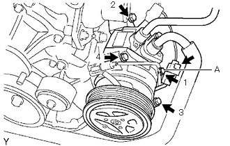
Temporarily install the compressor with the bolt labeled A.
Install the compressor completely by tightening the 4 bolts in the order shown in the illustration.
- Torque:
- 25 N*m (250 kgf*cm, 18 ft.*lbf)
- NOTICE:
-
In order to prevent misalignment, which causes belt rattle, tightening of the bolts must be performed in the order shown.
Connect the compressor connector.
Install the suction hose with the bolt.
- Torque:
- 5.4 N*m (55 kgf*cm, 48 in.*lbf)
4.INSTALL FAN AND GENERATOR V BELT (w/ Air Conditioning System)