1GR-FE ENGINE MECHANICAL CYLINDER HEAD GASKET REMOVAL
PROCEDURE

 1.REMOVE TIMING CHAIN COVER SUB-ASSEMBLY
2.REMOVE REAR WATER BY-PASS JOINT
3.SET NO. 1 CYLINDER TO TDC/COMPRESSION
4.REMOVE NO. 1 CHAIN TENSIONER ASSEMBLY
5.REMOVE CHAIN TENSIONER SLIPPER
6.REMOVE NO. 1 IDLE GEAR SHAFT
7.REMOVE NO. 2 CHAIN VIBRATION DAMPER
8.REMOVE CHAIN SUB-ASSEMBLY
9.REMOVE NO. 1 CHAIN VIBRATION DAMPER
10.REMOVE CAMSHAFT TIMING GEARS AND NO. 2 CHAIN (for Bank 1)
11.REMOVE NO. 2 CHAIN TENSIONER ASSEMBLY
12.REMOVE CAMSHAFT TIMING GEARS AND NO. 2 CHAIN (for Bank 2)
13.REMOVE CAMSHAFT AND NO. 2 CAMSHAFT
14.REMOVE CYLINDER HEAD SUB-ASSEMBLY
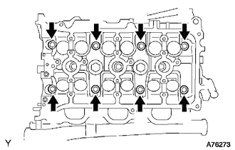
Using a 10 mm bi-hexagon wrench, uniformly loosen the 8 cylinder head bolts in the sequence shown in the illustration. Remove the 8 cylinder head bolts and plate washers.
- NOTICE:
- ·
Be careful not to drop the plate washers into the cylinder head.
·Cylinder head warpage or cracking could result from removing bolts in the incorrect order.
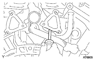
Lift the cylinder head from the dowels on the cylinder block and place the cylinder head on wooden blocks on a bench.
- NOTICE:
-
Be careful not to damage the contact surfaces of the cylinder head and cylinder block.
- HINT:
-
If the cylinder head is difficult to lift off, pry between the cylinder head and cylinder block with a screwdriver.
15.REMOVE NO. 1 CAMSHAFT BEARING
16.REMOVE NO. 2 CAMSHAFT BEARING
17.REMOVE CYLINDER HEAD GASKET
18.REMOVE NO. 3 CHAIN TENSIONER ASSEMBLY
19.REMOVE NO. 3 CAMSHAFT SUB-ASSEMBLY AND NO. 4 CAMSHAFT SUB-ASSEMBLY
20.REMOVE CYLINDER HEAD LH
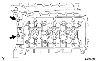
Uniformly loosen and remove the 2 cylinder head bolts in the sequence shown in the illustration.
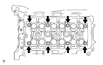
Using a 10 mm bi-hexagon wrench, uniformly loosen the 8 cylinder head bolts in the sequence shown in the illustration. Remove the 8 cylinder head bolts and plate washers.
- NOTICE:
- ·
Be careful not to drop the plate washers into the cylinder head LH.
·Cylinder head warpage or cracking could result from removing bolts in the incorrect order.
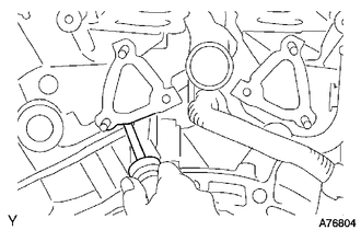
Lift the cylinder head from the dowels on the cylinder block and place the cylinder head LH on wooden blocks on a bench.
- NOTICE:
-
Be careful not to damage the contact surfaces of the cylinder head LH and cylinder block.
- HINT:
-
If the cylinder head LH is difficult to lift off, pry between the cylinder head LH and cylinder block with a screwdriver.
21.REMOVE NO. 2 CYLINDER HEAD GASKET
22.INSPECT CYLINDER HEAD SET BOLT
23.INSPECT CYLINDER HEAD SUB-ASSEMBLY