2TR-FBE FUEL FUEL SENDER GAUGE ASSEMBLY(for Fuel Sub Tank) INSTALLATION
PROCEDURE

 1.INSTALL FUEL SUCTION PLATE SUB-ASSEMBLY
Install a new fuel suction tube set gasket.
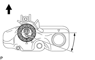
| *a | 5° to 15° |

|
Front Side |
Set the fuel suction plate sub-assembly to the auxiliary fuel tank shown in the illustration.
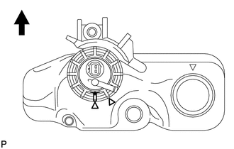
| *1 | Start Mark |
| *2 | Mark |
|
|
Front Side |
While holding the fuel suction plate sub-assembly by hand to prevent it from tilting, align the mark on the new fuel pump gauge retainer with the start mark on the auxiliary fuel tank and tighten the fuel pump gauge retainer 720° by hand.
- NOTICE:
-
Perform this work by hand. Do not use any tools.
2.CONNECT NO. 4 FUEL HOSE
Connect the No. 4 fuel hose.
Connect the fuel sender gauge connector.
3.ADD FUEL
4.CONNECT CABLE TO NEGATIVE BATTERY TERMINAL
- NOTICE:
-
When disconnecting the cable, some systems need to be initialized after the cable is reconnected (See page General>INTRODUCTION>REPAIR INSTRUCTION>INITIALIZATION).
5.INSPECT FOR FUEL LEAK (for Fuel Sub Tank)