RM1840EF
_51
Engine / Hybrid System
_009584
1KD-FTV EMISSION CONTROL
_0052297
DIFFERENTIAL PRESSURE SENSOR
A
1KD-FTV EMISSION CONTROL DIFFERENTIAL PRESSURE SENSOR INSTALLATION
PROCEDURE

 1.INSTALL DIFFERENTIAL PRESSURE SENSOR ASSEMBLY
a.
0.938,2.313 1.844,2.313
1.844,2.313 1.844,2.5
true
1.479,2.313 1.479,2.49
false
2.396,3.167 1.854,3.167
1.854,3.167 1.854,2.938
false
0.948,3.167 1.49,3.167
1.49,3.167 1.49,2.948
false
2.396,0.74 2.792,0.74
false
2.583,0.74 2.583,0.938
false
2.51,0.219 2.563,0.219
2.563,0.219 2.677,0.521
false
0.385,1.208 0.573,1.365
0.188,0.156
10
false
*a
2.115,1.219 2.302,1.375
0.188,0.156
10
false
*a
2.323,0.135 2.51,0.292
0.188,0.156
10
false
*d
1.146,1.198 1.333,1.354
0.188,0.156
10
false
*b
2.896,1.208 3.083,1.365
0.188,0.156
10
false
*b
0.729,2.229 0.917,2.385
0.188,0.156
10
false
*1
2.396,3.073 2.583,3.229
0.188,0.156
10
false
*2
0.74,3.083 0.927,3.24
0.188,0.156
10
false
*3
2.5,0.969 2.688,1.125
0.188,0.156
10
false
*4
1.708,0.583 1.865,0.74
0.156,0.156
10
false
*c
| *1 | Marking |
| *2 | Green Paint Mark |
| *3 | Orange Paint Mark |
| *4 | New Clip |
| *a | CORRECT |
| *b | INCORRECT |
| *c | 14.3 mm (0.562 in.) or less |
| *d | Clip must not protrude past end of hose |
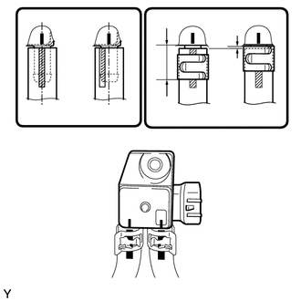
Install 2 new clips, the No. 6 exhaust pipe air hose and No. 7 exhaust pipe air hose to the differential pressure sensor.
- HINT:
- ·
Connect the air hoses so that the paint marks of the air hoses are as shown in the illustration.
·Make sure the clips are as shown in the illustration.
b.
Install the differential pressure sensor with the nut.
- Torque:
- 5.0 N*m (51 kgf*cm, 44 in.*lbf)
c.
Connect the connector.
2.INSTALL NO. 1 FRONT FLOOR HEAT INSULATOR
a.
Install the No. 1 front floor heat insulator with the 3 nuts.
- Torque:
- 5.0 N*m (51 kgf*cm, 44 in.*lbf)
3.INSTALL FRONT EXHAUST PIPE ASSEMBLY