1KD-FTV INTAKE / EXHAUST EXHAUST MANIFOLD W/ TURBOCHARGER(w/ DPF) REMOVAL
PROCEDURE

 1. PRECAUTION
- NOTICE:
-
After turning the ignition switch off, waiting time may be required before disconnecting the cable from the battery terminal. Therefore, make sure to read the disconnecting the cable from the battery terminal notice before proceeding with work (See page General>INTRODUCTION>REPAIR INSTRUCTION>PRECAUTION).
2.DISCONNECT CABLE FROM NEGATIVE BATTERY TERMINAL
- NOTICE:
-
When disconnecting the cable, some systems need to be initialized after the cable is reconnected (See page General>INTRODUCTION>REPAIR INSTRUCTION>INITIALIZATION).
3.REMOVE FRONT EXHAUST PIPE ASSEMBLY
4.REMOVE INTERCOOLER ASSEMBLY
5.REMOVE NO. 1 ENGINE UNDER COVER
6.REMOVE NO. 2 ENGINE UNDER COVER
7.DRAIN ENGINE COOLANT
8.REMOVE FRONT WHEEL RH
9.REMOVE FRONT FENDER APRON SEAL UPPER
Remove the 5 clips and front fender apron seal upper.
10.REMOVE FRONT FENDER SEAL
Remove the 5 clips and front fender seal.
11.REMOVE AIR CLEANER ASSEMBLY
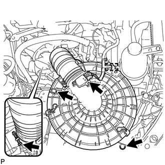
Detach the wire harness clamp and disconnect the mass air flow meter connector.
Loosen the hose clamp and disconnect No. 1 air cleaner hose from the compressor inlet elbow.
Remove the 2 bolts and air cleaner together with the No. 1 air cleaner hose.
12.REMOVE VENTILATION PIPE
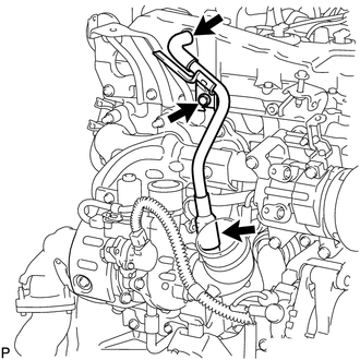
Remove the bolt and disconnect the 2 ventilation hoses and ventilation pipe.
13.REMOVE NO. 1 TURBO INSULATOR
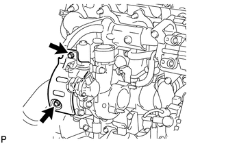
Remove the 2 bolts and No. 1 turbo insulator.
14.REMOVE NO. 1 EXHAUST MANIFOLD HEAT INSULATOR
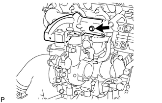
Remove the bolt and No. 1 exhaust manifold heat insulator.
15.REMOVE NO. 2 EXHAUST MANIFOLD HEAT INSULATOR
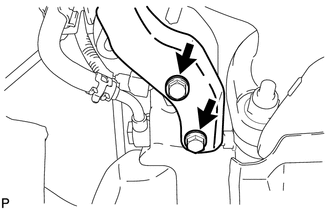
Remove the 2 bolts and No. 2 exhaust manifold heat insulator.
16.REMOVE NO. 3 EXHAUST MANIFOLD HEAT INSULATOR
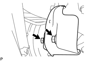
Remove the 2 bolts and No. 3 exhaust manifold heat insulator.
17.REMOVE TURBINE OUTLET ELBOW STAY
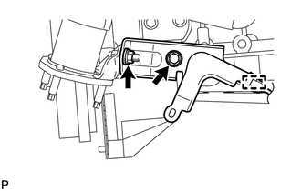
Detach the wire harness clamp and remove the bolt, nut and turbine outlet elbow stay.
18.REMOVE NO. 2 TURBINE OUTLET ELBOW
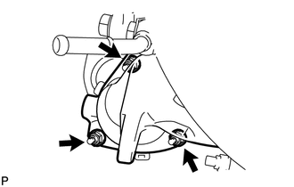
Remove the 3 nuts, No. 2 turbine outlet elbow and gasket.
19.DISCONNECT NO. 1 FUEL PIPE
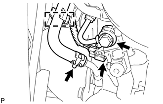
Detach the hose clamp and disconnect the No. 4 turbo water hose from the No. 4 water by-pass pipe.
Disconnect the exhaust fuel addition injector connector.
Remove the union bolt and gasket.
Disconnect the No. 1 fuel pipe from the turbine outlet elbow.
20.REMOVE TURBINE OUTLET ELBOW
Disconnect the No. 3 turbo water hose from the No. 3 water by-pass pipe.
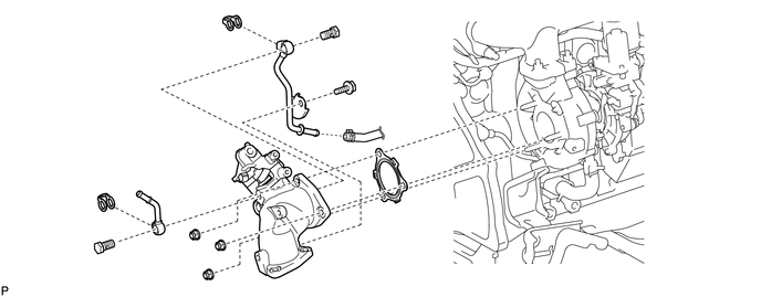
| *1 | Gasket | *2 | Union Bolt |
| *3 | No. 3 Water By-pass Pipe | *4 | No. 4 Water By-pass Pipe |
| *5 | No. 3 Turbo Water Hose | *6 | Turbine Outlet Elbow |
Remove the 3 nuts, turbine outlet elbow and gasket.
Remove the bolt, union bolt, gasket and No. 3 water by-pass pipe from the turbine outlet elbow.
Remove the union bolt, gasket and No. 4 water by-pass pipe from the turbine outlet elbow.
21.DISCONNECT NO. 1 TURBO WATER HOSE
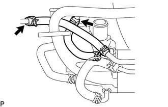
Disconnect the No. 1 turbo water hose and No. 9 water by-pass hose.
22.REMOVE TURBOCHARGER STAY
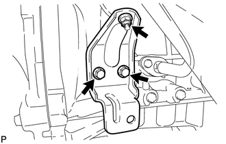
Remove the 2 bolts, nut and turbocharger stay.
23.REMOVE TURBO OIL INLET PIPE SUB-ASSEMBLY
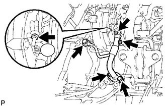
Remove the 2 bolts, 2 nuts, union bolt, turbo oil inlet pipe and 3 gaskets.
- NOTICE:
-
Do not loosen the nut labeled A in the illustration.
24.REMOVE TURBOCHARGER SUB-ASSEMBLY
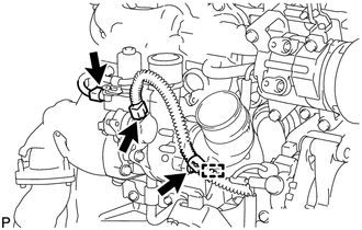
Disconnect the 2 connectors and detach the wire harness clamp.
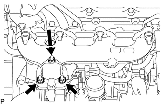
Remove the 3 nuts, turbocharger and gasket.
25.REMOVE NO. 1 TURBO WATER PIPE SUB-ASSEMBLY
Disconnect the No. 2 water by-pass hose from the compressor inlet elbow.
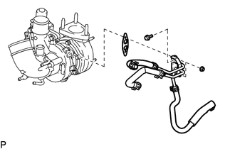
Remove the 2 nuts, bolt, No. 1 turbo water pipe and gasket from the turbocharger sub-assembly.
26.REMOVE COMPRESSOR INLET ELBOW
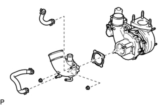
Remove the No. 7 water by-pass hose and No. 9 water by-pass hose from the compressor inlet elbow.
Remove the 2 nuts, compressor inlet elbow and gasket from the turbocharger sub-assembly.