2KD-FTV COOLING WATER PUMP(w/ DPF) INSTALLATION
CAUTION / NOTICE / HINT
- NOTICE:
- ·
When replacing the injectors (including shuffling the injectors between the cylinders), common rail or cylinder head, it is necessary to replace the injection pipes with new ones.
·When replacing the fuel supply pump, common rail, cylinder block, cylinder head, cylinder head gasket or timing gear case, it is necessary to replace the fuel inlet pipe with a new one.
·After removing the injection pipes, clean them with a brush and compressed air.
PROCEDURE

 1.INSTALL WATER PUMP ASSEMBLY
Install a new gasket and the water pump with the 5 bolts and 2 nuts.
- Torque:
- 13 N*m (133 kgf*cm, 10 ft.*lbf)
2.INSTALL NO. 2 TIMING BELT COVER
3.INSTALL CAMSHAFT TIMING PULLEY
4.INSTALL NO. 1 TIMING BELT IDLER SUB-ASSEMBLY
5.INSTALL TIMING BELT
6.INSTALL NO. 1 TIMING BELT COVER
7.INSTALL V-RIBBED BELT TENSIONER ASSEMBLY
8.INSTALL GENERATOR BRACKET
9.INSTALL GENERATOR ASSEMBLY
10.INSTALL NO. 2 IDLE PULLEY ASSEMBLY
11.CONNECT COOLER COMPRESSOR ASSEMBLY (w/ Air Conditioning System)
12.INSTALL FAN SHROUD
Install the fan pulley to the water pump.
Install the fan shroud together with the fluid coupling with fan between the radiator and engine component.
- NOTICE:
-
Be careful not to damage the radiator core.
Install the fluid coupling with fan to the fan pulley with the 4 nuts.
Tighten the nuts as much as possible by hand.
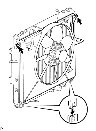
Attach the claws of the fan shroud to the radiator.
Install the fan shroud with the 2 bolts.
- Torque:
- 5.0 N*m (51 kgf*cm, 44 in.*lbf)
Install the fan and generator V belt (See page Engine / Hybrid System>2KD-FTV ENGINE MECHANICAL>DRIVE BELT>INSTALLATION).
Tighten the 4 nuts of the fluid coupling with fan.
- Torque:
- 23 N*m (235 kgf*cm, 17 ft.*lbf)
Install the radiator reservoir with the 2 bolts.
- Torque:
- 5.0 N*m (51 kgf*cm, 44 in.*lbf)
Connect the No. 1 and No. 2 water by-pass hoses to the radiator.
Install the oil reservoir with the 3 bolts.
- Torque:
- 4.5 N*m (46 kgf*cm, 40 in.*lbf)
13.INSTALL RADIATOR HOSE INLET
14.INSTALL CYLINDER HEAD COVER SUB-ASSEMBLY
15.INSTALL NO. 2 CYLINDER HEAD COVER SUB-ASSEMBLY
16.INSTALL NO. 4 INJECTION PIPE SUB-ASSEMBLY
17.INSTALL ELECTRIC EGR CONTROL VALVE ASSEMBLY WITH NO. 2 EGR VALVE AND EGR COOLER
18.CONNECT CABLE TO NEGATIVE BATTERY TERMINAL
- NOTICE:
-
When disconnecting the cable, some systems need to be initialized after the cable is reconnected (See page General>INTRODUCTION>REPAIR INSTRUCTION>INITIALIZATION).
19.BLEED AIR FROM FUEL SYSTEM
20.ADD ENGINE COOLANT
21.INSPECT FOR COOLANT LEAK
22.INSPECT FOR FUEL LEAK
23.INSPECT FOR OIL LEAK
24.INSTALL NO. 1 ENGINE UNDER COVER