Home › Drivetrain › A750F AUTOMATIC TRANSMISSION / TRANSAXLE › AUTOMATIC TRANSMISSION SYSTEM(for 1GR-FE) › 2012.04–2012.10
RM1840EF _52 Drivetrain _009612 A750F AUTOMATIC TRANSMISSION / TRANSAXLE _0052492 AUTOMATIC TRANSMISSION SYSTEM(for 1GR-FE) C

A750F AUTOMATIC TRANSMISSION / TRANSAXLE  AUTOMATIC TRANSMISSION SYSTEM(for 1GR-FE)  P2716  Pressure Control Solenoid "D" Electrical (Shift Solenoid Valve SLT)  


DESCRIPTION
C221301
4.885,2.063 5.208,1.125 5.208,1.125 5.271,1.125 true 5.031,2.208 5.188,2.573 5.188,2.573 5.26,2.573 true 5.875,2.271 6,2.573 6,2.573 6.063,2.573 true 6.115,2.479 7,2.698 0.885,0.219 10 false Solenoid Coil 0.104,0.677 1.354,0.896 1.25,0.219 10 false Hydraulic Pressure 2.563,3.01 3.125,3.229 0.563,0.219 10 false Current 5.313,2.49 5.844,2.708 0.531,0.219 10 false Sleeve 5.323,1.031 6.167,1.25 0.844,0.219 10 false Spool Valve

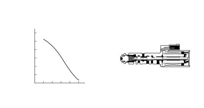
Shift solenoid valve SLT controls the transmission line pressure for smooth transmission operation based on signals from the throttle position sensor and vehicle speed sensor. The ECM adjusts the current to shift solenoid valve SLT to control the hydraulic line pressure coming from the primary regulator valve. Appropriate line pressure assures smooth shifting with varying engine outputs.

DTC No. Detection Item DTC Detection Condition Trouble Area MIL Memory
P2716 Pressure Control Solenoid "D" Electrical (Shift Solenoid Valve SLT) Open or short is detected in the shift solenoid valve SLT circuit for 1 sec. or more while driving (1-trip detection logic).
·

Open or short in shift solenoid valve SLT circuit

·

Shift solenoid valve SLT

·

ECM


Comes on DTC stored

MONITOR DESCRIPTION

When an open or short in the shift solenoid valve (SLT) circuit is detected, the ECM interprets this as a fault. The ECM will turn on the MIL and store the DTC.

WIRING DIAGRAM
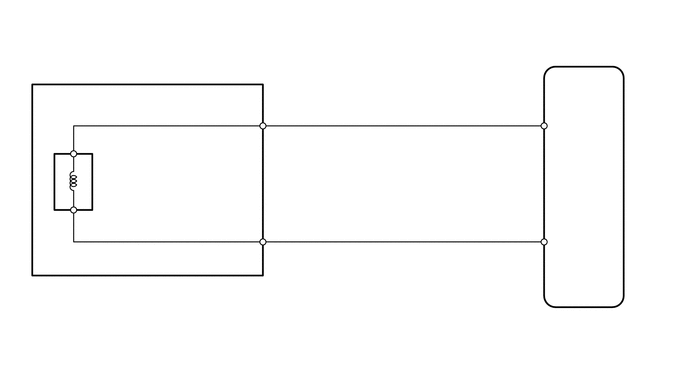
C220887
2.792,1.323 3.021,1.49 0.229,0.167 10 false 14 5.469,1.333 5.698,1.5 0.229,0.167 10 false 13 2.302,1.115 2.729,1.313 0.427,0.198 10 false SLT+ 2.771,2.542 3,2.708 0.229,0.167 10 false 6 2.333,2.313 2.76,2.51 0.427,0.198 10 false SLT- 5.771,1.229 6.198,1.427 0.427,0.198 10 false SLT+ 5.469,2.542 5.698,2.708 0.229,0.167 10 false 12 5.781,2.438 6.208,2.635 0.427,0.198 10 false SLT- 0.969,2.927 1.396,3.125 0.427,0.198 10 false C151 0.969,3.094 2.813,3.292 1.844,0.198 10 false Transmission Wire 1.042,1.781 2.698,2.01 1.656,0.229 10 false Shift Solenoid Valve SLT 5.99,3.25 6.333,3.417 0.344,0.167 10 false C130 5.99,3.406 6.417,3.604 0.427,0.198 10 false ECM 0.802,1.427 1.031,1.594 0.229,0.167 10 false 2 0.823,2.208 1.052,2.375 0.229,0.167 10 false 1

PROCEDURE

1.INSPECT TRANSMISSION WIRE (SHIFT SOLENOID VALVE SLT)
a.
C214326
1.438,1.323 1.229,1.75 true 1.521,1.104 1.771,1.75 true 1.042,1.771 1.406,1.938 0.365,0.167 10 false SLT+ 0.052,0.021 0.281,0.188 0.229,0.167 10 false *a 1.677,1.771 2.021,1.938 0.344,0.167 10 false SLT-
*a Component without harness connected
(Transmission Wire)


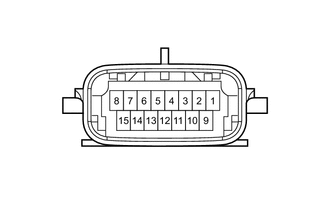
Disconnect the transmission wire connector.


b.

Measure the resistance according to the value(s) in the table below.

Standard Resistance:
Tester Connection Condition Specified Condition
14 (SLT+) - 6 (SLT-) 20°C (68°F) 5.0 to 5.6 Ω
14 (SLT+) - Body ground Always 10 kΩ or higher
6 (SLT-) - Body ground Always 10 kΩ or higher


Result:
Proceed to
OK
NG


OK

2.CHECK HARNESS AND CONNECTOR (TRANSMISSION WIRE - ECM)

NG

3.INSPECT SHIFT SOLENOID VALVE SLT
2.CHECK HARNESS AND CONNECTOR (TRANSMISSION WIRE - ECM)
a.
C237600
0.896,0.333 1.302,0.573 0.406,0.24 1.198,2.052 1.594,2.813 true 1.135,2.052 0.698,2.823 true 1.354,2.896 2.073,3.219 0.719,0.323 10 false 12 (SLT-) 0.938,0.365 1.302,0.563 0.365,0.198 10 false C130 0.094,0.052 0.375,0.385 0.281,0.333 10 false *a 0.365,2.885 1.021,3.135 0.656,0.25 10 false 13 (SLT+)
*a Rear view of wire harness connector
(to ECM)


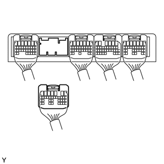
Disconnect the ECM connector.


b.

Measure the resistance according to the value(s) in the table below.

Standard Resistance:
Tester Connection Condition Specified Condition
C130-13 (SLT+) - C130-12 (SLT-) 20°C (68°F) 5.0 to 5.6 Ω
C130-13 (SLT+) - Body ground Always 10 kΩ or higher
C130-12 (SLT-) - Body ground Always 10 kΩ or higher


Result:
Proceed to
OK
NG


OK

NG

REPAIR OR REPLACE HARNESS OR CONNECTOR

3.INSPECT SHIFT SOLENOID VALVE SLT
a.
C209928
1.771,0.969 2.219,0.385 true 1.479,0.958 1.021,0.375 true 1.771,2.948 2.219,2.354 true 1.479,2.948 1.021,2.354 true 0.052,0 0.365,0.198 0.313,0.198 10 false *a 2.25,0.26 2.417,0.458 0.167,0.198 10 false 1 0.917,0.24 1.083,0.438 0.167,0.198 10 false 2 2.24,2.208 2.406,2.406 0.167,0.198 10 false 1 0.917,2.229 1.083,2.427 0.167,0.198 10 false 2 1.927,3.979 2.125,4.177 0.198,0.198 10 false (-) 1.115,3.99 1.333,4.188 0.219,0.198 10 false (+)
*a Component without harness connected
(Shift Solenoid Valve SLT)


Remove shift solenoid valve SLT.


b.

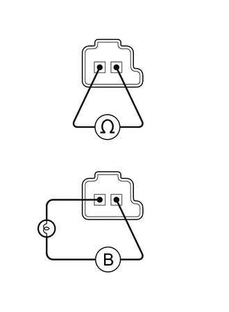
Measure the resistance according to the value(s) in the table below.

Standard Resistance:
Tester Connection Condition Specified Condition
1 -2 20°C (68°F) 5.0 to 5.6 Ω


c.

Apply 12 V battery voltage to the shift solenoid valve and check that the valve moves and makes an operating noise.

OK:
Measurement Condition Specified Condition
·

Battery positive (+) with a 21 W bulb → Terminal 2

·

Battery negative (-) → Terminal 1


Valve moves and makes operating noise


Result:
Proceed to
OK
NG


OK

NG