BRAKE CONTROL / DYNAMIC CONTROL SYSTEMS FRONT SPEED SENSOR(for 4WD and Pre-Runner) INSTALLATION
CAUTION / NOTICE / HINT
- HINT:
- ·
The procedure listed below is for the LH side.
·Other than areas where instructions are provided, use the same procedure for the LH and RH sides.
PROCEDURE

 1.INSTALL SKID CONTROL SENSOR CLAMP LH
Install the skid control sensor clamp with the bolt.
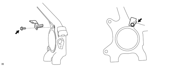
| *a | Stopper | - | - |
- Torque:
- 14 N*m (138 kgf*cm, 10 ft.*lbf)
- NOTICE:
-
Install the clamp so that the rotation stopper touches the knuckle.
2.INSTALL SKID CONTROL SENSOR CLAMP RH
Install the skid control sensor clamp with the bolt.
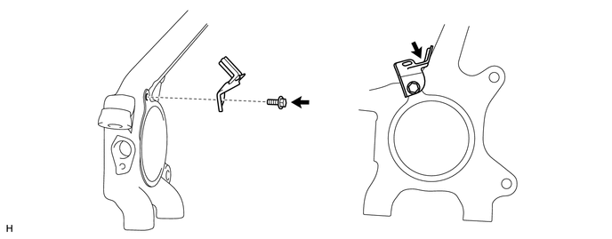
| *a | Stopper | - | - |
- Torque:
- 14 N*m (138 kgf*cm, 10 ft.*lbf)
- NOTICE:
-
Install the clamp so that the rotation stopper touches the knuckle.
3.INSTALL FRONT SPEED SENSOR LH
Install the speed sensor with the bolt.
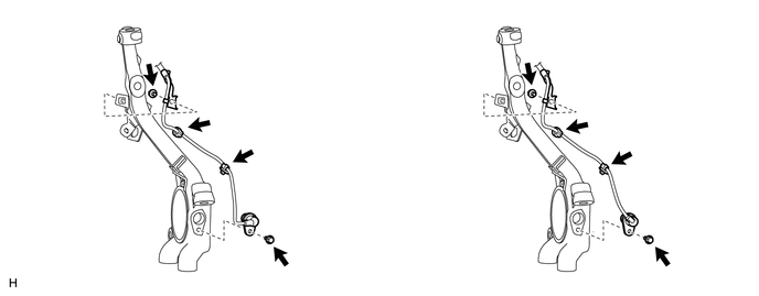
| *A | w/ VSC | *B | w/o VSC |
- Torque:
- 8.5 N*m (87 kgf*cm, 75 in.*lbf)
- NOTICE:
- ·
Make sure there are no pieces of iron or other foreign matter attached to the sensor tip.
·While inserting the speed sensor into the knuckle hole, do not strike or damage the sensor tip.
·After installing the speed sensor, make sure there is no clearance or foreign matter between the sensor stay part and the knuckle.
·When installing the sensor, do not twist the wire harness.
Install the harness clamp with the bolt.
- Torque:
- 32 N*m (326 kgf*cm, 24 ft.*lbf)
- NOTICE:
- ·
When installing the clamp, do not twist the wire harness.
·Make sure the clamp rotation stopper touches the installation position.
Attach the 2 clamps.
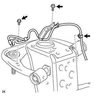
Attach the clamp.
Install the 2 harness clamps with the 2 bolts.
- Torque:
- 32 N*m (326 kgf*cm, 24 ft.*lbf)
- NOTICE:
- ·
When installing the clamps, do not twist the wire harness.
·Make sure the clamp rotation stopper touches the installation position.
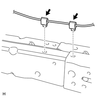
Attach the 2 clamps.
- NOTICE:
-
When attaching the clamps, do not twist the wire harness.
Connect the connector.
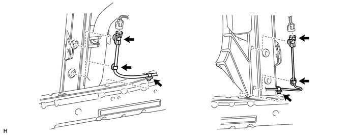
| *A | for LH | *B | for RH |
- NOTICE:
- ·
Do not attach the connector to the radiator fan shroud before connecting the connector.
·Securely connect the connector.
Attach the 2 clamps and the connector.
- NOTICE:
-
When attaching the clamps, do not twist the wire harness.
4.INSTALL FRONT WHEEL
5.CONNECT CABLE TO NEGATIVE BATTERY TERMINAL
- NOTICE:
-
When disconnecting the cable, some systems need to be initialized after the cable is reconnected (See page General>INTRODUCTION>REPAIR INSTRUCTION>INITIALIZATION).
6.CHECK SPEED SENSOR SIGNAL