THEFT DETERRENT / KEYLESS ENTRY THEFT DETERRENT SYSTEM Security Horn Circuit
DESCRIPTION
When the theft deterrent system is operating, a relay in the theft warning ECU assembly turns ON and OFF continuously at 0.4 seconds intervals, causing the security horn assembly to sound.
WIRING DIAGRAM
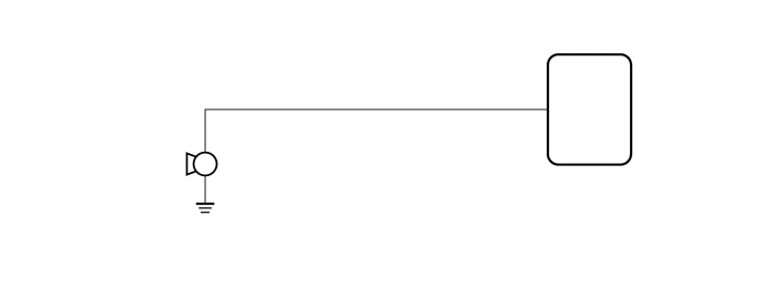
CAUTION / NOTICE / HINT
- NOTICE:
-
When replacing the theft warning ECU assembly, refer to the registration procedures (See page Vehicle Interior>DOOR LOCK>WIRELESS DOOR LOCK CONTROL SYSTEM(for Built-in Type Door Control Receiver)>REGISTRATION).
PROCEDURE
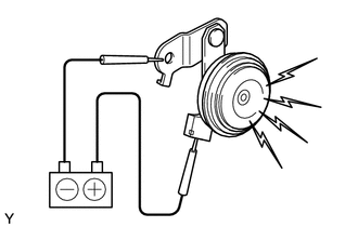
Remove the the security horn assembly.
Click hereVehicle Interior>THEFT DETERRENT / KEYLESS ENTRY>SECURITY HORN ASSEMBLY>REMOVAL
Apply battery voltage to the horn and check operation of the horn.
- OK:
Measurement Condition Specified Condition Battery positive (+) → Terminal 1
Battery negative (-) → Horn bracketHorn sounds
- Result:
Proceed to OK NG
OK
NG
Disconnect the G29 theft warning ECU assembly connector.
Disconnect the A25 security horn assembly connector.
Measure the resistance according to the value(s) in the table below.
- Standard Resistance:
Tester Connection Condition Specified Condition G29-13 (SH-) - A25-1 Always Below 1 Ω G29-13 (SH-) or A25-1 - Body ground Always 10 kΩ or higher
- Result:
Proceed to OK NG
OK
NG