HEATING / AIR CONDITIONING AIR CONDITIONING SYSTEM(for Automatic Air Conditioning System) 23 Pressure Switch Circuit
DESCRIPTION
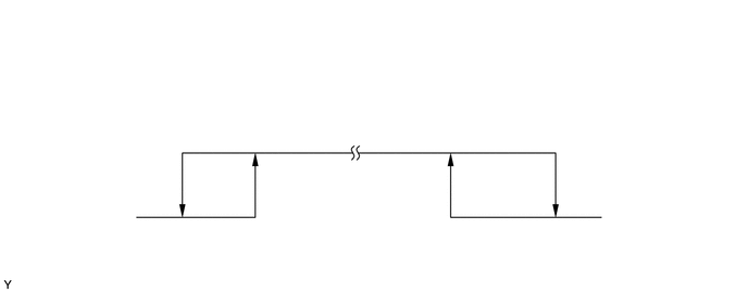
The air conditioner pressure sensor turns off when the air conditioning refrigerant pressure extremely (0.196 MPa [2.0 kgf/cm2], 28 psi] or less) or extremely high (3.14 MPa [32.0 kgf/cm2, 455 psi] or more). When the air conditioning amplifier assembly detects the off state of the air conditioner pressure sensor, the air conditioning amplifier assembly outputs signals to the magnet clutch relay to turn the magnet clutch off.
| DTC No. | Detection Item | DTC Detection Condition | Trouble Area | Memory | Note |
|---|---|---|---|---|---|
| 23 | Pressure Switch Circuit | When either condition below is met:
·
An open in air conditioner pressure sensor circuit ·
Abnormal refrigerant pressure: 0.196 MPa (2.0 kgf/cm2, 28 psi) or less 3.14 MPa (32.0 kgf/cm2, 455 psi) or high |
·
Air conditioner tube & accessory assembly (air conditioner pressure sensor) ·
Refrigerant and refrigerant pipe line ·
Air conditioning amplifier assembly ·
Harness or connector |
- | - |
WIRING DIAGRAM
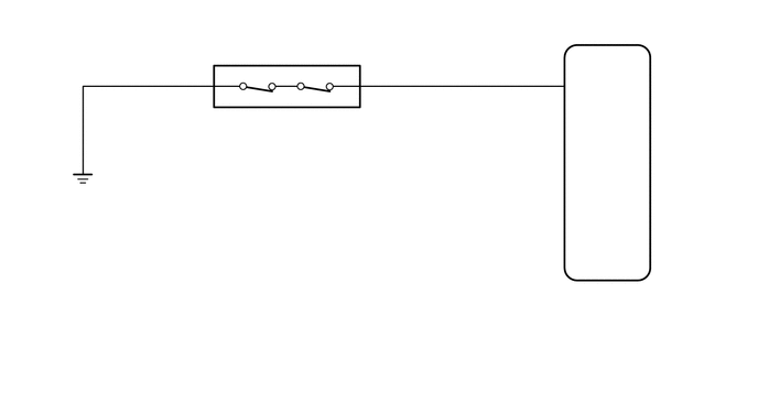
PROCEDURE
Install a manifold gauge.
Check refrigerant pressure.
Click hereVehicle Interior>HEATING / AIR CONDITIONING>REFRIGERANT>ON-VEHICLE INSPECTION
- Standard pressure:
Pressure on high-pressure side
1.37 to 1.57 MPa (13.9 to 16.0 kgf/cm2, 198 to 228 psi)
- HINT:
-
If the refrigerant pressure is below 0.196 MPa (2.0 kgf/cm2, 28 psi), the refrigerant amount in the air conditioning cycle may have decreased significantly due to gas leakage or other problems.
- Result:
Proceed to OK NG
OK
NG
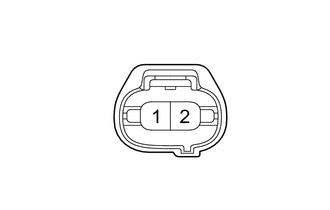
| *a | Front view of wire harness connector
(to Air Conditioner Pressure Sensor) |
Disconnect the A16 air conditioner pressure sensor connector.
Check the air conditioning operation.
- OK:
Measurement Condition Specified Condition ·Engine idling
·A/C switch on
·Blower switch on (LO level)
·Connect terminals A16-1 and A16-2
Magnet clutch is on ·Engine idling
·A/C switch on
·Blower switch on (LO level)
·Disconnect terminals A16-1 and A16-2
Magnet clutch is off
- Result:
Proceed to OK NG
OK
NG
Disconnect the A16 air conditioner pressure sensor connector.
Disconnect the G95 air conditioning amplifier assembly connector.
Measure the resistance according to the value(s) in the table below.
- Standard Resistance:
Tester Connection Condition Specified Condition A16-2 - G95-5 (PSW) Always Below 1 Ω A16-1 - Body ground G95-5 (PSW) - Body ground Always 10 kΩ or higher
- Result:
Result Proceed to OK (When troubleshooting according to problem symptoms table.) A OK (When troubleshooting according to DTC.) B NG C
A
B
C