DOOR / HATCH REAR DOOR REASSEMBLY
CAUTION / NOTICE / HINT
- HINT:
- ·
Use the same procedure for the RH and LH sides.
·The procedure listed below is for the LH side.
·A bolt without a torque specification is shown in the standard bolt chart (See page General>SPECIFICATIONS>STANDARD BOLT>SPECIFIED TORQUE FOR STANDARD BOLTS).
PROCEDURE

 1.INSTALL REAR DOOR CHECK ASSEMBLY LH
Apply MP grease to the sliding area of the rear door check.
When reusing a bolt labeled B:
Clean the threads of the bolt labeled B with non-residue solvent.
Apply adhesive to the threads of the bolt labeled B.
- Adhesive:
Toyota Genuine Adhesive 1324, Three Bond 1324 or equivalent.
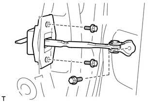
| *1 | Bolt A |
| *2 | Bolt B |
Install the rear door check with the 2 bolts labeled A and bolt labeled B.
- Torque:
- Bolt A : 5.5 N*m (56 kgf*cm, 49 in.*lbf)
- Bolt B : 30 N*m (306 kgf*cm, 22 ft.*lbf)
2.INSTALL REAR DOOR WEATHERSTRIP LH
- HINT:
-
When installing the rear door weatherstrip, heat the rear door panel using a heat light.
- Standard:
Item Temperature Rear Door Panel 40 to 60°C (104 to 140°F)
- NOTICE:
-
Do not heat the rear door panel excessively.
Clean the rear door panel surface.
Using a heat light, heat the rear door panel surface.
Remove the double-sided tape from the rear door panel surface.
Wipe off any tape adhesive residue with cleaner.
Install a new rear door weatherstrip.
Remove the peeling paper from the face of the rear door weatherstrip.
- HINT:
-
After removing the peeling paper, keep the exposed adhesive free from foreign matter.
Attach the 32 clips to install the rear door weatherstrip.
- HINT:
-
Press the rear door weatherstrip firmly to install it.
Install the clip.
3.INSTALL REAR DOOR PANEL CUSHION
Install a new rear door panel cushion.
4.INSTALL REAR DOOR REAR OUTSIDE HANDLE PAD
Attach the 2 claws to install the rear door rear outside handle pad.
5.INSTALL REAR DOOR FRONT OUTSIDE HANDLE PAD
Attach the 2 claws to install the rear door front outside handle pad.
6.INSTALL REAR DOOR OUTSIDE HANDLE FRAME SUB-ASSEMBLY LH
Apply MP grease to the sliding area of the rear door outside handle frame.
Using a T30 "TORX" socket wrench, install the rear door outside handle frame with the screw.
- Torque:
- 4.0 N*m (41 kgf*cm, 35 in.*lbf)
7.INSTALL REAR DOOR OUTSIDE HANDLE ASSEMBLY LH
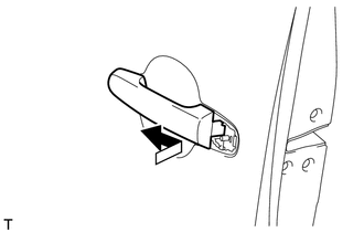
Install the rear door outside handle by moving it in the direction indicated by the arrow shown in the illustration.
8.INSTALL REAR DOOR OUTSIDE HANDLE COVER LH
Using a T30 "TORX" socket wrench, install the rear door outside handle with the screw.
- Torque:
- 4.0 N*m (41 kgf*cm, 35 in.*lbf)
9.INSTALL REAR DOOR INSIDE LOCKING CABLE ASSEMBLY LH
Install the rear door inside locking cable.
Attach the 3 claws to close the cover.
10.INSTALL REAR DOOR LOCK REMOTE CONTROL CABLE ASSEMBLY LH
Install the rear door lock remote control cable.
11.INSTALL REAR DOOR LOCK ASSEMBLY LH
w/ Power Door Lock:
(See page Vehicle Interior>DOOR LOCK>REAR DOOR LOCK>INSTALLATION)
w/o Power Door Lock:
Using a T30 "TORX" socket wrench, install the rear door lock with the 3 screws.
- Torque:
- 5.0 N*m (51 kgf*cm, 44 in.*lbf)
Connect the rear door inside locking cable and rear door lock remote control cable to the clamps.
12.INSTALL POWER WINDOW REGULATOR MOTOR ASSEMBLY LH (w/ Power Window)
13.INSTALL REAR DOOR WINDOW REGULATOR SUB-ASSEMBLY LH
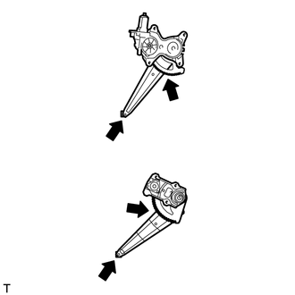
| *A | w/ Power Window |
| *B | w/o Power Window |
Apply MP grease to the sliding and rotating areas of the rear door window regulator.
- NOTICE:
-
Do not apply grease to the spring of the window regulator.
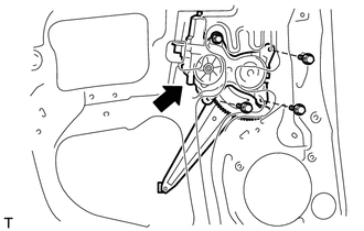
| *1 | Temporary Bolt |
w/ Power Window:
Temporarily install the temporary bolt to the rear door window regulator.
Install the rear door window regulator with the 3 bolts, and then tighten the temporary bolt.
- Torque:
- 8.0 N*m (82 kgf*cm, 71 in.*lbf)
- NOTICE:
-
Be careful not to drop the rear door window regulator as it may become damaged.
Connect the connector.
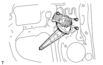
| *1 | Temporary Bolt |
w/o Power Window:
Temporarily install the temporary bolt to the rear door window regulator.
Install the rear door window regulator with the 2 bolts, and then tighten the temporary bolt.
- Torque:
- 8.0 N*m (82 kgf*cm, 71 in.*lbf)
- NOTICE:
-
Be careful not to drop the rear door window regulator as it may become damaged.
14.INSTALL REAR DOOR GLASS CHANNEL FILLER
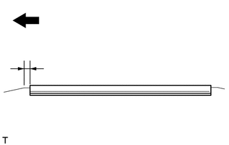
| *a | Front Side |
Install the rear door glass channel filler to the rear door glass as shown in the illustration.
- Standard:
Area Dimension A 10.7 mm (0.421 in.)
15.INSTALL REAR DOOR GLASS CHANNEL SUB-ASSEMBLY LH
Apply soapy water to the inside of the rear door glass channel.
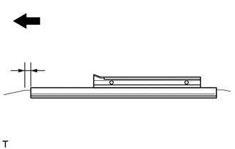
| *a | Front Side |
Using a plastic-faced hammer, tap the rear door glass channel onto the rear door glass to install the rear door glass channel as shown in the illustration.
- NOTICE:
-
Be careful not to damage the glass or glass channel.
- Standard:
Area Dimension A 10.7 mm (0.421 in.)
16.INSTALL REAR DOOR GLASS SUB-ASSEMBLY LH
w/ Power Window:
Temporarily install the rear power window regulator switch assembly with rear door armrest base panel.
Connect the cable to the negative (-) battery terminal.
Operate the rear door window regulator so that the rear door glass can be installed.
Disconnect the cable from the negative (-) battery terminal.
- NOTICE:
-
When disconnecting the cable, some systems need to be initialized after the cable is reconnected (See page General>INTRODUCTION>REPAIR INSTRUCTION>INITIALIZATION).
Remove the rear power window regulator switch assembly with rear door armrest base panel.
w/o Power Window:
Temporarily install the rear door window regulator handle.
Operate the rear door window regulator so that the rear door glass can be installed.
Remove the rear door window regulator handle.
Install the front side of the rear door glass run.
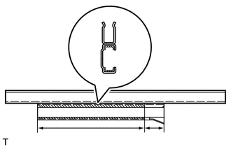
| *1 | MP Grease |
Apply MP grease to the sliding area of the rear door glass channel as shown in the illustration.
- Standard:
Area Specified Condition A 155 mm (6.10 in.) B 30 mm (1.18 in.)
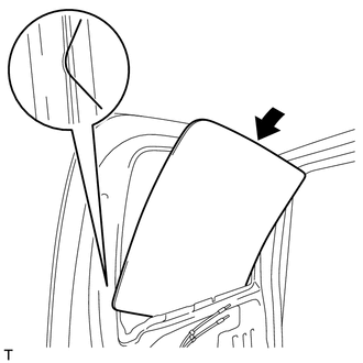
| *a | Rear Door Panel Cutout |
Install the rear door glass by passing it through the cutout of the rear door panel in the direction indicated by the arrow in the illustration.
- NOTICE:
-
Do not damage the door glass.
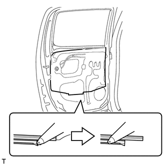
Install the rear door glass channel to the rear door window regulator as shown in the illustration.
- NOTICE:
-
Do not damage the door glass.
17.INSTALL REAR DOOR WINDOW DIVISION BAR SUB-ASSEMBLY LH
Align the rear door glass run with the rear door window division bar.
Install the rear door glass run together with the rear door window division bar with the 2 bolts.
18.INSTALL REAR DOOR GLASS RUN LH
Finish installing the rear door glass run.
19.INSTALL REAR DOOR SERVICE HOLE COVER LH
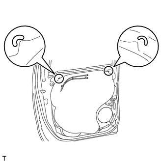
| *a | Reference Point |
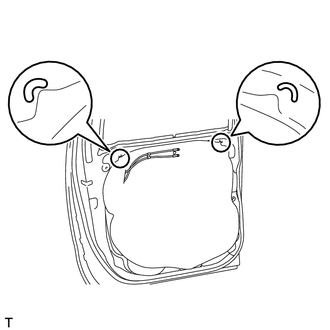
| *a | Reference Point |
w/ Rear Speaker:
Apply new butyl tape to the rear door panel.
Pass the rear door inside locking cable, rear door lock remote control cable and wire harness through a new rear door service hole cover, and then attach the rear door service hole cover using the reference points on the rear door panel.
- NOTICE:
- ·
Securely install the rear door service hole cover to prevent wrinkles and air bubbles.
·There should be no wrinkles or folds after installing the rear door service hole cover.
·After installing the rear door service hole cover, check the seal quality.
w/o Rear Speaker:
Apply new butyl tape to the rear door panel.
Pass the rear door inside locking cable and rear door lock remote control cable through a new rear door service hole cover, and then attach the rear door service hole cover using the reference points on the rear door panel.
- NOTICE:
- ·
Securely install the rear door service hole cover to prevent wrinkles and air bubbles.
·There should be no wrinkles or folds after installing the rear door service hole cover.
·After installing the rear door service hole cover, check the seal quality.
20.INSTALL REAR DOOR NO. 2 TRIM BRACKET
Install the rear door No. 2 trim bracket with the 2 screws.
21.INSTALL REAR DOOR INSIDE HANDLE SUB-ASSEMBLY LH
Connect the rear door inside locking cable and rear door lock remote control cable to the rear door inside handle.
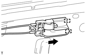
Attach the 2 guides as indicated by the arrow in the illustration, and then attach the claw to install the rear door inside handle.
22.INSTALL REAR SPEAKER ASSEMBLY (w/ Rear Speaker)
23.INSTALL REAR DOOR OUTER GLASS WEATHERSTRIP LH
24.INSTALL REAR DOOR INNER GLASS WEATHERSTRIP LH
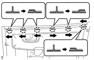
Install the rear door inner glass weatherstrip to the rear door trim panel and fold down the 6 claws in the directions indicated by the arrows in the illustration.
25.INSTALL REAR DOOR TRIM BOARD SUB-ASSEMBLY LH
Attach the 9 clips to install the rear door trim board.
Install the screw and clip.
26.INSTALL DOOR PULL HANDLE
Install the door pull handle with the screw.
27.INSTALL REAR POWER WINDOW REGULATOR SWITCH ASSEMBLY WITH REAR DOOR ARMREST BASE PANEL (w/ Power Window)
Connect the connector.
Attach the 2 claws and 2 clips to install the rear power window regulator switch assembly with rear door armrest base panel.
28.INSTALL REAR DOOR WINDOW REGULATOR HANDLE ASSEMBLY (w/o Power Window)
Temporarily install the rear door window regulator handle, fully close the window, and then remove the rear door window regulator handle.
Install the plate and snap ring to the rear door window regulator handle.
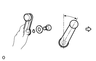
| *1 | Snap Ring |
| *2 | Plate |
| *a | Front Side |
Install the rear door window regulator handle to the rear door window regulator as shown in the illustration.
- Standard:
Area Specified Condition A 18 to 42°
29.CONNECT CABLE TO NEGATIVE BATTERY TERMINAL (w/ Power Window)
- NOTICE:
-
When disconnecting the cable, some systems need to be initialized after the cable is reconnected (See page General>INTRODUCTION>REPAIR INSTRUCTION>INITIALIZATION).