Home › Engine / Hybrid System › 1GR-FE ENGINE CONTROL › SFI SYSTEM › from 2012.10
RM1840EF _51 Engine / Hybrid System _009572 1GR-FE ENGINE CONTROL _0052127 SFI SYSTEM C

1GR-FE ENGINE CONTROL  SFI SYSTEM  P0230  Fuel Pump Primary Circuit  


DESCRIPTION

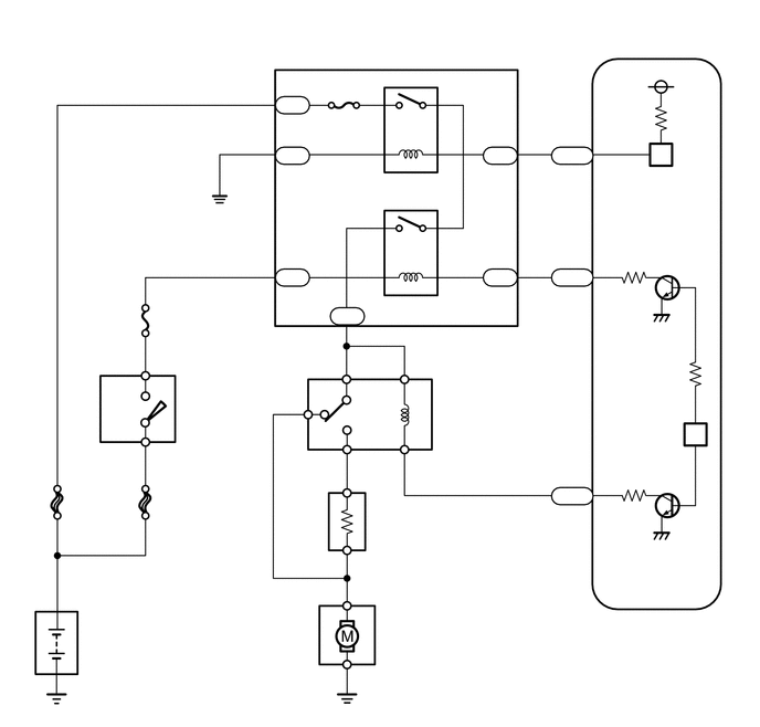
As shown in the illustration, when the engine is cranked, current flows from terminal ST1 of the ignition switch into the ECM and the ST relay coil.

When the STA signal and NE signal are input to the ECM, Tr1 (power transistor 1) is turned ON, current flows to the coil of the C/OPN relay, the relay switches on, power is supplied to the fuel pump, and the fuel pump operates.

While the NE signal is generated (engine running), the ECM keeps the Tr1 ON (C/OPN relay ON) and the fuel pump also keeps operating.

The fuel pump speed is controlled at two levels (high speed or low speed) by engine condition (starting, light load, heavy load). When the engine starts (STA ON), Tr2 (power transistor 2) in the ECM is OFF, so the F-PMP/FFV relay closes and positive battery voltage is applied directly to the fuel pump. The fuel pump operates at high speed.

During idling or under light loads, Tr2 goes ON, and then power is supplied to the fuel pump via the fuel pump resistor. The fuel pump operates at low speed.
A252547
2.563,2.479 2.844,2.635 0.281,0.156 10 false IGN 1.333,3.573 2.24,4.031 0.906,0.458 10 false Ignition Switch Assembly 0.583,6.146 1.083,6.375 0.5,0.229 10 false Battery 2.958,4.344 3.74,5.021 0.781,0.677 10 false Park/Neutral Position Switch Assembly 4.656,1.938 5.438,2.125 0.781,0.188 10 false F-PMP/FFV 5.927,0.823 6.375,1.01 0.448,0.188 10 false MREL 5.927,1.219 6.26,1.406 0.333,0.188 10 false FPR 6.25,6.813 6.635,7.01 0.385,0.198 10 false ECM 5.927,4.385 6.198,4.573 0.271,0.188 10 false FC 5.948,6.177 6.313,6.365 0.365,0.188 10 false STA 5.917,5.302 6.271,5.49 0.354,0.188 10 false NE+ 0.906,0.74 1.229,0.927 0.323,0.188 10 false EFI 4.885,2.281 5.406,2.854 0.521,0.573 10 false Fuel Pump Resistor 0.615,3.375 1.01,3.531 0.396,0.156 10 false AM2 1.229,6.74 1.802,6.896 0.573,0.156 10 false Starter 5.906,5.708 6.26,5.865 0.354,0.156 10 false NSW 2.104,5.365 2.365,5.521 0.26,0.156 10 false ST 2.448,4.333 2.604,4.49 0.156,0.156 10 false B 2.188,4.583 2.365,4.76 0.177,0.177 10 false P 2.729,4.333 2.885,4.49 0.156,0.156 10 false L 2.177,4.823 2.354,5 0.177,0.177 10 false N 5.26,3.823 5.656,4.208 0.396,0.385 10 false Fuel Pump 3.052,2.135 3.635,2.354 0.583,0.219 10 false C/OPN 6.479,4.375 6.75,4.563 0.271,0.188 10 false Tr1 6.625,1.24 6.896,1.427 0.271,0.188 10 false Tr2 4.792,5.417 5.563,5.646 0.771,0.229 10 false NE Signal 1.896,1.125 2.333,1.292 0.438,0.167 10 false MAIN 2.354,3.469 2.646,3.646 0.292,0.177 10 false ST 0.448,2.542 1.365,2.698 0.917,0.156 10 false BATT P/I

DTC No. Detection Item DTC Detection Condition Trouble Area MIL Memory
P0230 Fuel Pump Primary Circuit Open or short in F-PMP/FFV relay circuit
(1 trip detection logic)
·

Open or short in fuel pump relay circuit

·

F-PMP/FFV relay

·

ECM


- DTC stored

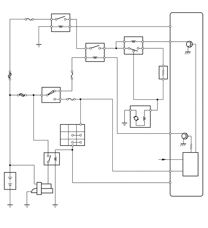
WIRING DIAGRAM

A279105
1.723,3.677 2.361,4.239 0.639,0.562 10 Ignition Switch Assembly 1.723,3.527 2.004,3.682 0.281,0.156 10 G9 3.141,1.04 3.436,1.223 0.295,0.184 10 EFI 3.933,3.113 5.459,3.297 1.526,0.184 10 No. 1 Integration Relay 4.129,3.786 5.007,3.969 0.878,0.184 10 F-PMP/FFV 5.338,4.425 5.573,4.593 0.235,0.168 10 30 3.518,4.869 4.873,5.053 1.354,0.184 10 Fuel Pump Resistor 3.518,4.736 3.876,4.906 0.357,0.170 10 A76 2.995,2.896 3.148,3.048 0.152,0.152 10 8 2.715,2.364 2.868,2.516 0.152,0.152 10 6 3.333,6.305 3.485,6.457 0.152,0.152 10 5 3.333,4.259 3.485,4.412 0.152,0.152 10 5 3.331,4.45 3.483,4.602 0.152,0.152 10 1 3.342,5.212 3.494,5.364 0.152,0.152 10 2 3.877,3.399 4.029,3.551 0.152,0.152 10 2 3.333,3.399 3.509,3.576 0.177,0.177 10 3 3.888,4.259 4.041,4.412 0.152,0.152 10 1 3.333,5.518 3.509,5.694 0.177,0.177 10 4 2.76,3.724 2.937,3.901 0.177,0.177 10 4 3.615,5.964 4.416,6.155 0.802,0.191 10 Fuel Pump 3.615,5.803 3.972,5.987 0.357,0.184 10 L4 1.467,2.936 1.747,3.092 0.281,0.156 10 IGN 0.798,5.958 1.311,6.138 0.514,0.180 10 Battery 5.366,1.215 5.519,1.367 0.152,0.152 10 8 4.685,1.215 4.861,1.392 0.177,0.177 10 2 3.684,1.642 4.118,1.826 0.434,0.184 10 MAIN 4.685,2.371 4.841,2.539 0.156,0.168 10 7 5.222,1.381 5.634,1.556 0.412,0.176 10 G155 5.223,2.532 5.612,2.702 0.389,0.170 10 G155 5.223,4.591 5.612,4.761 0.389,0.170 10 C131 5.656,1.22 6.101,1.411 0.445,0.191 10 MREL 5.32,2.371 5.555,2.539 0.235,0.168 10 10 2.676,0.904 2.891,1.074 0.215,0.170 10 1H 2.676,1.38 2.891,1.550 0.215,0.170 10 1J 2.676,2.529 2.891,2.699 0.215,0.170 10 1J 3.195,2.893 3.410,3.063 0.215,0.170 10 1J 4.638,2.529 4.853,2.699 0.215,0.170 10 1J 4.638,1.38 4.853,1.550 0.215,0.170 10 1J 5.662,4.427 5.999,4.616 0.337,0.188 10 FPR 6.005,5.82 6.392,6.020 0.387,0.200 10 ECM 5.684,2.371 5.958,2.561 0.274,0.191 10 FC 1.455,4.654 1.847,4.810 0.392,0.156 10 AM2 1.244,4.199 1.397,4.351 0.152,0.152 10 5 2.715,1.22 2.930,1.373 0.215,0.152 10 3 1.23,3.358 1.383,3.511 0.152,0.152 10 6 1.081,3.559 1.397,3.715 0.316,0.156 10 IG2 1.025,3.979 1.417,4.135 0.392,0.156 10 AM2 3.649,2.803 4.232,3.025 0.583,0.222 10 C/OPN 2.701,0.737 2.878,0.913 0.177,0.177 10 1 0.637,4.655 1.246,4.828 0.609,0.173 10 BATT P/I

CAUTION / NOTICE / HINT

HINT:
·

This DTC chart is based on the premise that the engine is started normally. If the engine is difficult to start, proceed to the problem symptoms table (See page Engine / Hybrid System>1GR-FE ENGINE CONTROL>SFI SYSTEM>PROBLEM SYMPTOMS TABLE).

·

Read freeze frame data using an intelligent tester. Freeze frame data records the engine condition when malfunctions are detected. When troubleshooting, freeze frame data can help determine if the vehicle was moving or stationary, if the engine was warmed up or not, if the air fuel ratio was lean or rich, and other data from the time the malfunction occurred.


PROCEDURE
1.INSPECT ECM (FPR VOLTAGE)
a.
A253413
1.51,0.969 1.938,1.219 0.427,0.25 1.698,1.979 1.396,2.51 true 0.99,2.531 1.615,2.698 0.625,0.167 10 30 (FPR) 0.26,0.177 0.479,0.365 0.219,0.188 10 *a 1.573,1 1.99,1.188 0.417,0.188 10 C131
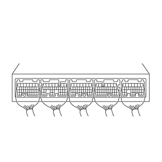
*a Component with harness connected
(ECM)


Measure the voltage according to the value(s) in the table below.

Standard Voltage:
Tester Connection Condition Specified Condition
C131-30 (FPR) - Body ground STA signal ON 11 to 14 V
STA signal OFF
(engine idling)
Below 3 V


Result:
Proceed to
OK
NG


OK

NG

2.INSPECT RELAY (F-PMP/FFV)

Result:
Proceed to
OK
NG


OK

3.CHECK HARNESS AND CONNECTOR (F-PMP/FFV RELAY - ECM, NO. 1 INTEGRATION RELAY)

NG

REPLACE RELAY (F-PMP/FFV)

3.CHECK HARNESS AND CONNECTOR (F-PMP/FFV RELAY - ECM, NO. 1 INTEGRATION RELAY)
a.

Remove the F-PMP/FFV relay from the engine room relay block and junction block assembly.


b.

Remove the No. 1 integration relay from the engine room relay block and junction block assembly.


c.

Disconnect the ECM connector.


d.

Measure the resistance according to the value(s) in the table below.

Standard Resistance:
Tester Connection Condition Specified Condition
F-PMP/FFV relay terminal 1 - C131-30 (FPR) Always Below 1 Ω
F-PMP/FFV relay terminal 2 - 1J-8 Always Below 1 Ω
F-PMP/FFV relay terminal 1 or C131-30 (FPR) - Body ground Always 10 kΩ or higher
F-PMP/FFV relay terminal 2 or 1J-8 - Body ground Always 10 kΩ or higher


Result:
Proceed to
OK
NG


OK

NG

REPAIR OR REPLACE HARNESS OR CONNECTOR