2TR-FBE ENGINE CONTROL SFI SYSTEM P1604 Startability Malfunction
DESCRIPTION
If the engine does not start or it takes a long time for the engine to start although the STA signal is input to the ECM, this DTC will be stored.
Read freeze frame data using the intelligent tester. The ECM records vehicle and driving condition information as freeze frame data the moment a DTC is stored. When troubleshooting, freeze frame data can be helpful in determining whether the vehicle was moving or stationary, whether the engine was warmed up or not, whether the air fuel ratio was lean or rich, as well as other data recorded at the time of a malfunction.
It is necessary to check if the vehicle has run out of fuel before starting diagnosis because this DTC is also stored due to running out of fuel.
| DTC No. | Detection Item | DTC Detection Condition | Trouble Area | MIL | Memory |
|---|---|---|---|---|---|
| P1604 | Startability Malfunction | Either of the conditions is met (1 trip detection logic):
·
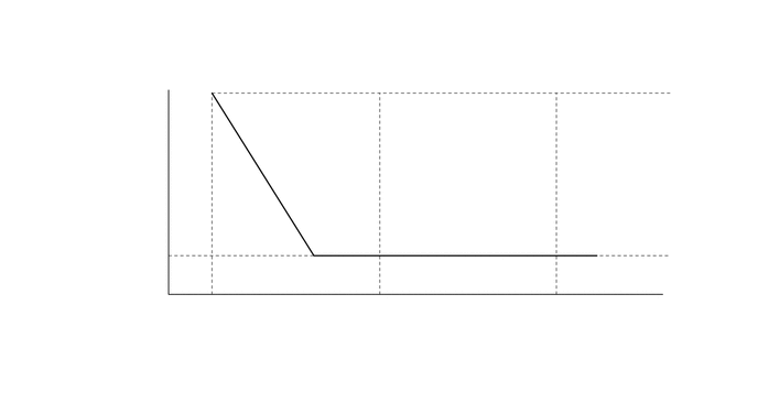
The engine speed is below 500 rpm with the STA signal on for a certain amount of time (refer to the illustration below) ·
After the engine starts (engine speed is 500 rpm or more), the engine speed drops to 200 rpm or less within approximately 2 seconds |
·
Immobiliser system ·
Engine unit (excessive friction, decreased compression) ·
Starter system ·
Crankshaft position sensor circuit ·
Engine coolant temperature sensor circuit ·
Fuel pump (for fuel main tank) ·
Fuel pump control circuit ·
Fuel line ·
Fuel injector assembly circuit ·
Throttle body with motor assembly ·
Pressure regulator ·
Battery ·
Drive plate ·
Spark plug ·
Ignition coil assembly circuit ·
Intake system connection ·
Camshaft timing oil control valve assembly ·
Mass air flow meter sub-assembly ·
Air fuel ratio sensor (sensor 1) ·
Heated oxygen sensor (sensor 2) ·
Valve timing ·
Camshaft position sensor ·
Fuel ·
Purge VSV ·
Sub tank fuel pump control circuit ·
Fuel pump (for fuel sub tank) ·
Fuel jet ·
Solenoid valve assembly (for fuel injection volume control) ·
Solenoid valve assembly (for fuel cut control) ·
ECM |
Does not come on | DTC stored |
CAUTION / NOTICE / HINT
- HINT:
- ·
In contrast to normal malfunction diagnosis for components, circuits and systems, DTC P1604 is used to determine the malfunctioning area from the problem symptoms and freeze frame data when the user mentions problems such as starting difficulty.
As this DTC can be stored as a result of certain user actions, even if this DTC is output, if the customer makes no mention of problems, clear this DTC without performing any troubleshooting and return the vehicle to the customer.
·If any DTCs other than P1604 are output, troubleshoot those DTCs first.
·Since DTC P1604 is different from other DTCs, the following procedure is shown as a reference.
·Read freeze frame data using the intelligent tester. The ECM records vehicle and driving condition information as freeze frame data the moment a DTC is stored. When troubleshooting, freeze frame data can be helpful in determining whether the vehicle was moving or stationary, whether the engine was warmed up or not, whether the air fuel ratio was lean or rich, as well as other data recorded at the time of a malfunction.
PROCEDURE
Check if the engine cranks.
- Result:
Result Proceed to The engine cranks A The engine does not crank B
A
B
Connect the intelligent tester to the DLC3.
Turn the ignition switch to ON.
Turn the tester on.
Enter the following menus: Powertrain / Engine and ECT / DTC.
- Powertrain > Engine and ECT > Trouble Codes
- 50001 234
Read the DTCs.
- Result:
Result Proceed to DTC P1604 is output A DTC P1604 and other DTCs are output B
- HINT:
-
If any DTCs other than P1604 are output, troubleshoot those DTCs first.
A
B
Connect the intelligent tester to the DLC3.
Turn the ignition switch to ON.
Turn the tester on.
Check the following freeze frame data to see the state of the battery when the freeze frame data was recorded.
| Battery Voltage |
Check the following freeze frame data to see if the engine was cranking when the freeze frame data was recorded.
| Engine Speed |
| Fuel Pump/Speed Status |
Check the following freeze frame data to check the temperature data recorded when the engine did not start normally.
| Coolant Temp |
| Intake Air |
Check the following freeze frame data to see the engine operating conditions recorded when the engine started.
| MAF |
Check the following freeze frame data to see the air fuel ratio recorded when the engine started.
| Long FT #1 |
Check the following freeze frame data to see the FFV (Flexible Fuel Vehicle) information recorded when the engine did not start normally.
| Alcohol Feedback Value |
| Alc FB Val bfr F/Crrctn by Stall |
| Trip aft F/Crrctn by Stall |
| Fuel Dilution Estimate |
Use this information to perform a simulation test.
Compare the "Normal Condition" information in the Data List (reference values) with the freeze frame data listed above and with the simulation test results to determine the problem cause.
- Result:
Result Proceed to The problem cause can be determined A The problem cause cannot be determined B
A
B