RM1840EF
_57
Power Source / Network
_009639
NETWORKING
_0052677
CAN COMMUNICATION SYSTEM(w/ VSC)
J
NETWORKING CAN COMMUNICATION SYSTEM(w/ VSC) ECM Communication Stop Mode
DESCRIPTION
| Detection Item | Symptom | Trouble Area |
|---|---|---|
| ECM Communication Stop Mode | Either condition is met:
·
"ECM (Engine)" is not displayed on the "Bus Check" screen. ·
"ECM Communication Stop Mode" in "DTC Communication Table" applies. |
·
Power source or inside of ECM ·
ECM |
WIRING DIAGRAM
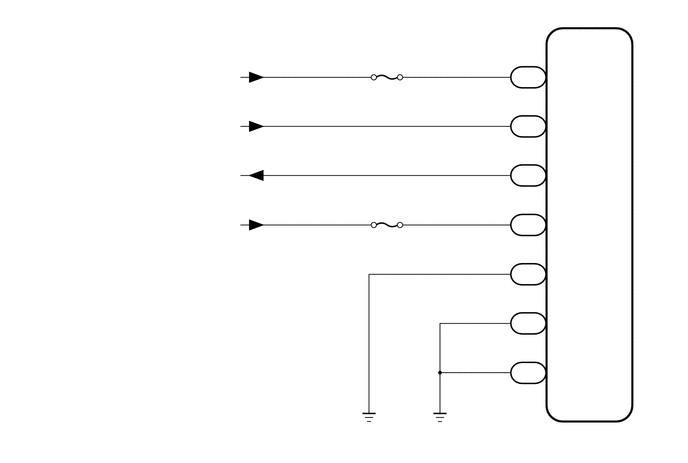
5.958,4.469 6.385,4.677
0.427,0.208
10
false
ECM
5.76,3.281 6.125,3.448
0.365,0.167
10
false
E01
5.771,2.771 6.167,2.938
0.396,0.167
10
false
E1
5.75,3.802 6.115,4.021
0.365,0.219
10
false
E02
5.771,1.781 6.271,2.052
0.5,0.271
10
false
MREL
5.771,2.281 6.25,2.49
0.479,0.208
10
false
IGSW
5.375,2.25 5.688,2.458
0.313,0.208
10
false
G39
5.469,2.042 5.719,2.479
0.25,0.438
10
false
9
5.375,1.74 5.667,1.927
0.292,0.188
10
false
G39
5.479,1.531 5.677,1.802
0.198,0.271
10
false
8
5.375,1.229 5.677,1.406
0.302,0.177
10
false
G39
5.458,1.031 5.625,1.26
0.167,0.229
10
false
1
5.375,3.802 5.677,4.031
0.302,0.229
10
false
C22
5.469,3.594 5.635,3.771
0.167,0.177
10
false
6
5.385,3.281 5.677,3.469
0.292,0.188
10
false
C22
5.479,3.083 5.688,3.281
0.208,0.198
10
false
7
5.385,2.771 5.667,2.927
0.281,0.156
10
false
C23
5.479,2.573 5.74,2.844
0.26,0.271
10
false
7
5.375,0.708 5.771,0.938
0.396,0.229
10
false
G38
5.479,0.51 5.635,0.708
0.156,0.198
10
false
2
5.76,1.24 5.958,1.427
0.198,0.188
10
false
+B
5.76,0.719 6.188,0.917
0.427,0.198
10
false
BATT
1.427,1.208 2.521,1.5
1.094,0.292
10
false
from MAIN Relay
1.688,0.708 2.521,0.958
0.833,0.25
10
false
from Battery
3.938,0.573 4.25,0.823
0.313,0.25
10
false
EFI
3.917,2.115 4.26,2.365
0.344,0.25
10
false
IGN
1.563,1.719 2.552,2.042
0.99,0.323
10
false
to MAIN Relay
1.24,2.24 2.594,2.531
1.354,0.292
10
false
from Ignition Switch
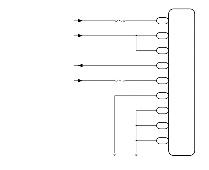
6.073,5.375 6.573,5.688
0.5,0.313
10
false
ECM
5.406,4.74 5.823,4.958
0.417,0.219
10
false
C164
5.5,4.521 5.74,4.76
0.24,0.24
10
false
12
5.854,4.74 6.344,5.063
0.49,0.323
10
false
E02
5.406,4.229 5.865,4.469
0.458,0.24
10
false
C164
5.5,4.01 5.729,4.208
0.229,0.198
10
false
11
5.854,4.219 6.323,4.615
0.469,0.396
10
false
E01
5.406,3.198 5.813,3.396
0.406,0.198
10
false
G157
5.5,2.979 5.74,3.198
0.24,0.219
10
false
11
5.854,3.188 6.344,3.49
0.49,0.302
10
false
EC
5.406,2.677 5.802,2.896
0.396,0.219
10
false
G156
5.5,2.479 5.729,2.688
0.229,0.208
10
false
24
5.854,2.677 6.406,2.958
0.552,0.281
10
false
IGSW
5.406,2.167 5.833,2.396
0.427,0.229
10
false
G156
5.5,1.948 5.76,2.177
0.26,0.229
10
false
11
5.854,2.167 6.448,2.49
0.594,0.323
10
false
MREL
5.406,1.646 5.823,1.906
0.417,0.26
10
false
G156
5.5,1.438 5.75,1.646
0.25,0.208
10
false
17
5.854,1.646 6.375,1.917
0.521,0.271
10
false
+B2
5.406,1.146 5.813,1.396
0.406,0.25
10
false
G156
5.5,0.938 5.802,1.188
0.302,0.25
10
false
24
5.854,1.135 6.354,1.385
0.5,0.25
10
false
+B
5.406,0.615 5.906,0.896
0.5,0.281
10
false
G156
5.5,0.427 5.823,0.729
0.323,0.302
10
false
23
5.854,0.625 6.385,0.906
0.531,0.281
10
false
BATT
5.406,3.698 5.833,3.948
0.427,0.25
10
false
C164
5.5,3.49 5.76,3.708
0.26,0.219
10
false
13
5.854,3.708 6.313,4.042
0.458,0.333
10
false
ME01
4.01,0.479 4.427,0.771
0.417,0.292
10
false
EFI
1.74,0.635 2.635,0.99
0.896,0.354
10
false
from Battery
1.438,1.156 2.646,1.458
1.208,0.302
10
false
from MAIN Relay
1.281,2.698 2.594,3.094
1.313,0.396
10
false
from Ignition Switch
1.604,2.188 2.635,2.531
1.031,0.344
10
false
to MAIN Relay
3.979,2.552 4.427,2.844
0.448,0.292
10
false
IGN
0.156,0.094 2.156,0.406
2,0.313
12
false
for 1KD-FTV (w/ i-ART):
CAUTION / NOTICE / HINT
- NOTICE:
-
Inspect the fuses for circuits related to this system before performing the following inspection procedure.
PROCEDURE
1.CHECK HARNESS AND CONNECTOR (ECM - BATTERY AND BODY GROUND)
a.
for 1KD-FTV:
i.
Disconnect the C22, C23, G38 and G39 ECM connectors.
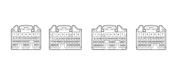
0.865,0.667 1.313,0.917
0.448,0.25
2.438,0.667 2.885,0.917
0.448,0.25
4.344,0.667 4.792,0.917
0.448,0.25
6.094,0.667 6.542,0.917
0.448,0.25
0.677,1.646 0.938,2.167
0.938,2.167 1.031,2.167
true
0.552,2.323 0.427,2.323
0.427,2.323 0.573,1.646
true
0.563,0.917 0.677,0.917
0.677,0.917 0.604,1.375
true
2.198,0.917 2.302,0.917
2.302,0.917 2.448,1.385
true
5.302,1.063 5.198,1.063
5.198,1.063 5.115,1.385
true
6.781,0.927 6.667,0.927
6.667,0.927 6.781,1.375
true
6.625,1.479 6.792,2.219
6.792,2.219 6.708,2.219
true
0.969,0.719 1.25,0.865
0.281,0.146
10
false
G39
2.552,0.719 2.865,0.906
0.313,0.188
10
false
G38
4.448,0.719 4.729,0.875
0.281,0.156
10
false
C23
6.208,0.719 6.479,0.896
0.271,0.177
10
false
C22
0.063,0.052 0.344,0.323
0.281,0.271
10
false
*a
0.375,0.823 0.573,0.969
0.198,0.146
10
false
+B
1.854,0.844 2.229,0.99
0.375,0.146
10
false
BATT
5.323,0.99 5.51,1.135
0.188,0.146
10
false
E1
6.802,0.854 7.073,1
0.271,0.146
10
false
E01
0.573,2.24 1,2.385
0.427,0.146
10
false
MREL
1.063,2.094 1.49,2.24
0.427,0.146
10
false
IGSW
6.438,2.135 6.708,2.281
0.271,0.146
10
false
E02
| *a | Front view of wire harness connector
(to ECM) |
- | - |
ii.
Measure the voltage according to the value(s) in the table below.
- Standard Voltage:
Tester Connection Condition Specified Condition G38-2 (BATT) - Body ground Always 11 to 14 V G39-1 (+B) - Body ground Battery positive (+) voltage applied to terminal G39-8 (MREL) 11 to 14 V G39-9 (IGSW) - Body ground Ignition switch ON 11 to 14 V
iii.
Measure the resistance according to the value(s) in the table below.
- Standard Resistance:
Tester Connection Condition Specified Condition C23-7 (E1) - Body ground Always Below 1 Ω C22-7 (E01) - Body ground Always Below 1 Ω C22-6 (E02) - Body ground Always Below 1 Ω
b.
for 1KD-FTV (w/ i-ART):
i.
Disconnect the C164, G156 and G157 ECM connectors.
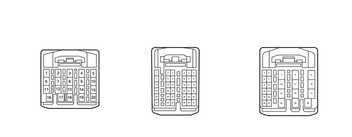
1.208,0.635 1.604,0.896
0.396,0.26
3.354,0.594 3.75,0.854
0.396,0.26
5.677,0.583 6.073,0.844
0.396,0.26
0.906,2.417 1.167,1.865
true
0.75,2.229 0.938,1.865
true
1.563,2.333 1.406,1.865
true
4.094,2.146 3.958,1.875
true
6.125,2.521 6.01,2.156
true
6.448,2.344 6.271,2.146
true
6.021,1.688 6.375,1.25
true
6.333,1.844 6.49,1.656
true
0.583,2.24 0.75,2.24
false
0.729,2.417 0.896,2.417
false
1.573,2.333 1.74,2.333
false
4.104,2.146 4.271,2.146
false
3.833,1.573 4.135,1.104
true
4.146,1.104 4.313,1.104
false
6.125,2.521 6.292,2.521
false
6.458,2.344 6.625,2.344
false
6.5,1.656 6.667,1.656
false
6.375,1.25 6.542,1.25
true
1.24,0.688 1.615,0.875
0.375,0.188
10
false
C164
3.375,0.635 3.833,0.854
0.458,0.219
10
false
G156
5.708,0.625 6.167,0.823
0.458,0.198
10
false
G157
0.167,0.115 0.365,0.302
0.198,0.188
10
false
*a
0.323,2.125 0.698,2.313
0.375,0.188
10
false
E01
0.469,2.385 0.844,2.573
0.375,0.188
10
false
E02
1.813,2.25 2.188,2.438
0.375,0.188
10
false
ME01
4.365,2.063 4.833,2.25
0.469,0.188
10
false
IGSW
4.344,1.021 4.844,1.229
0.5,0.208
10
false
MREL
6.583,1.167 6.958,1.354
0.375,0.188
10
false
EC
6.698,1.563 7.073,1.75
0.375,0.188
10
false
+B2
6.688,2.26 6.979,2.469
0.292,0.208
10
false
+B
6.406,2.448 6.865,2.646
0.458,0.198
10
false
BATT
| *a | Front view of wire harness connector
(to ECM) |
- | - |
ii.
Measure the voltage according to the value(s) in the table below.
- Standard Voltage:
Tester Connection Condition Specified Condition G157-23 (BATT) - Body ground Always 11 to 14 V G157-24 (+B) - Body ground Battery positive (+) voltage applied to terminal G156-11 (MREL) 11 to 14 V G157-17 (+B2) - Body ground Battery positive (+) voltage applied to terminal G156-11 (MREL) 11 to 14 V G156-24 (IGSW) - Body ground Ignition switch ON 11 to 14 V
iii.
Measure the resistance according to the value(s) in the table below.
- Standard Resistance:
Tester Connection Condition Specified Condition G157-11 (EC1) - Body ground Always Below 1 Ω C164-13 (ME01) - Body ground Always Below 1 Ω C164-11 (E01) - Body ground Always Below 1 Ω C164-12 (E02) - Body ground Always Below 1 Ω
- Result:
Proceed to OK NG
OK
NG
REPAIR OR REPLACE HARNESS OR CONNECTOR