RM1840EF
_51
Engine / Hybrid System
_009608
CRUISE CONTROL
_0052446
CRUISE CONTROL SYSTEM
J
CRUISE CONTROL CRUISE CONTROL SYSTEM TC and CG Terminal Circuit
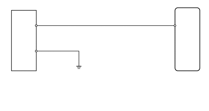
WIRING DIAGRAM
6.271,2.469 6.615,2.615
0.344,0.146
10
G39
6.073,0.802 6.438,0.948
0.365,0.146
10
TC
1.313,1.583 1.677,1.729
0.365,0.146
10
4
0.99,0.802 1.354,0.948
0.365,0.146
10
TC
0.979,1.667 1.344,1.813
0.365,0.146
10
CG
1.302,0.698 1.667,0.844
0.365,0.146
10
13
5.781,0.688 5.969,0.844
0.188,0.156
10
11
0.625,2.479 0.979,2.635
0.354,0.156
10
G18
0.625,2.656 1.01,2.802
0.385,0.146
10
DLC3
6.271,2.615 6.615,2.76
0.344,0.146
10
ECM
PROCEDURE
1.CHECK HARNESS AND CONNECTOR (DLC3 - ECM AND BODY GROUND)
a.
Disconnect the G39 ECM connector.
b.
Measure the resistance according to the value(s) in the table below.
- Standard Resistance:
Tester Connection Condition Specified Condition G18-13 (TC) - G39-11 (TC) Always Below 1 Ω G18-4 (CG) - Body ground G18-13 (TC) - Body ground Always 10 kΩ or higher
- Result:
Proceed to OK NG
OK
NG
REPAIR OR REPLACE HARNESS OR CONNECTOR