BRAKE CONTROL / DYNAMIC CONTROL SYSTEMS VEHICLE STABILITY CONTROL SYSTEM C0226 SFR Solenoid Circuit C0236 SFL Solenoid Circuit C0246 SRR Solenoid Circuit C0256 SRL Solenoid Circuit C1225 SM Solenoid Circuit
DESCRIPTION
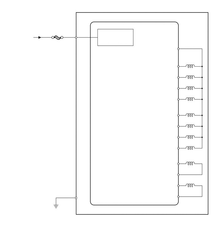
These solenoids turn on when signals are received from the skid control ECU (brake actuator assembly) and control the pressure acting on the wheel cylinders to control the braking force.
| DTC No. | Detection Item | DTC Detection Condition | Trouble Area |
|---|---|---|---|
| C0226 | SFR Solenoid Circuit | An open or short in the solenoid circuit continues for 0.05 seconds or more. | ·
Solenoid circuit ·
Brake actuator assembly |
| C0236 | SFL Solenoid Circuit | An open or short in the solenoid circuit continues for 0.05 seconds or more. | ·
Solenoid circuit ·
Brake actuator assembly |
| C0246 | SRR Solenoid Circuit | An open or short in the solenoid circuit continues for 0.05 seconds or more. | ·
Solenoid circuit ·
Brake actuator assembly |
| C0256 | SRL Solenoid Circuit | An open or short in the solenoid circuit continues for 0.05 seconds or more. | ·
Solenoid circuit ·
Brake actuator assembly |
| C1225 | SM Solenoid Circuit | One of the following conditions is met:
1.
While a master cylinder cut solenoid (SM1 or SM2) is on, overcurrent continues for 0.1 seconds or more. 2.
While a master cylinder cut solenoid (SM1 or SM2) is off, an open circuit continues for 0.05 seconds or more. 3.
While a master cylinder cut solenoid (SM1 or SM2) is on, an open circuit continues for 0.05 seconds or more. 4.
While a master cylinder cut solenoid (SM1 or SM2) is off, current continues to be applied for 0.05 seconds or more. 5.
A condition in which the outputs from master cylinder cut solenoids 1 and 2 are different continues for 0.2 seconds or more. |
·
SM1 or SM2 circuit ·
Brake actuator assembly |
WIRING DIAGRAM
CAUTION / NOTICE / HINT
- NOTICE:
-
After replacing the brake actuator assembly, perform calibration (See page Brake>BRAKE CONTROL / DYNAMIC CONTROL SYSTEMS>VEHICLE STABILITY CONTROL SYSTEM>CALIBRATION).
PROCEDURE
- HINT:
-
These codes are stored when a problem is detected in the skid control ECU (brake actuator assembly). The solenoid circuits are in the skid control ECU (brake actuator assembly). Therefore, solenoid circuit inspections and solenoid unit inspections cannot be performed. Be sure to check if any DTCs are output before replacing the brake actuator assembly.
Clear the DTCs.
Click hereBrake>BRAKE CONTROL / DYNAMIC CONTROL SYSTEMS>VEHICLE STABILITY CONTROL SYSTEM>DTC CHECK / CLEAR
- Chassis > ABS/VSC/TRC > Clear DTCs
- 50002 105
Turn the ignition switch off.
Start the engine.
Drive the vehicle at a speed of 20 km/h (12 mph) or more for 30 seconds or more.
Check if the same DTC is output.
Click hereBrake>BRAKE CONTROL / DYNAMIC CONTROL SYSTEMS>VEHICLE STABILITY CONTROL SYSTEM>DTC CHECK / CLEAR
- Chassis > ABS/VSC/TRC > Trouble Codes
- 50001 105
- Result:
Result Proceed to DTC is not output A DTC is output B
- HINT:
- ·
If a speed signal of 6 km/h (4 mph) or more is input to the skid control ECU (brake actuator assembly) with the ignition switch ON and the stop light switch off, the ECU performs self-diagnosis of the motor and solenoid circuits.
·If the normal system code is output (the trouble code is not output), slightly jiggle the connectors, wire harnesses and fuses of the skid control ECU (brake actuator assembly). Make sure that no DTCs are output.
·If any DTCs are output while jiggling a connector or wire harness of the skid control ECU (brake actuator assembly), inspect and repair the connector or wire harness. The DTCs were probably stored due to a bad connection of the connector terminal.
A
Click hereGeneral>INTRODUCTION>HOW TO TROUBLESHOOT ECU CONTROLLED SYSTEMS>HOW TO PROCEED WITH TROUBLESHOOTING
B