1KD-FTV ENGINE CONTROL ECD SYSTEM(for i-ART) P167A Lost Communication with Injector #1 P167B Lost Communication with Injector #2 P167C Lost Communication with Injector #3 P167D Lost Communication with Injector #4
DESCRIPTION
| DTC No. | Detection Item | DTC Detection Condition | Trouble Area | MIL | Memory |
|---|---|---|---|---|---|
| P167A | Lost Communication with Injector #1 | Communication between the ECM and injector assembly is lost for 4 seconds or more.
(1 trip detection logic) |
·
No. 1 Injector assembly ·
Harness and connector |
Comes on | DTC stored |
| P167B | Lost Communication with Injector #2 | Communication between the ECM and injector assembly is lost for 4 seconds or more.
(1 trip detection logic) |
·
No. 2 Injector assembly ·
Harness and connector |
Comes on | DTC stored |
| P167C | Lost Communication with Injector #3 | Communication between the ECM and injector assembly is lost for 4 seconds or more.
(1 trip detection logic) |
·
No. 3 Injector assembly ·
Harness and connector |
Comes on | DTC stored |
| P167D | Lost Communication with Injector #4 | Communication between the ECM and injector assembly is lost for 4 seconds or more.
(1 trip detection logic) |
·
No. 4 Injector assembly ·
Harness and connector |
Comes on | DTC stored |
CONFIRMATION DRIVING PATTERN
| DTC Detection Drive Pattern | Ignition switch ON for 3 minutes or more |
MONITOR DESCRIPTION
If the ECM detects that there is a communication problem with an injector for a certain amount of time continuously, it illuminates the MIL.
A DTC is assigned for each cylinder. However, the cylinders cannot be distinguished. If there is no problem with the communication line, replace all the injector assemblies.
- HINT:
-
If there is a problem with the communication line, the fuel temperature for the cylinder which has a communication problem does not change when "Fuel Temperature" is confirmed in the Data List.
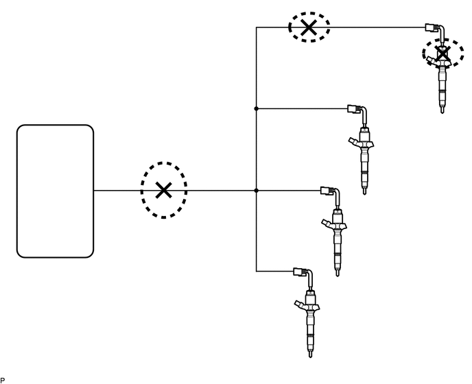
WIRING DIAGRAM
Refer to DTC P0201 (See page Engine / Hybrid System>1KD-FTV ENGINE CONTROL>ECD SYSTEM(for i-ART)>P0201).
CAUTION / NOTICE / HINT
- HINT:
-
Read freeze frame data using the GTS. Freeze frame data records the engine condition when malfunctions are detected. When troubleshooting, freeze frame data can help determine if the vehicle was moving or stationary, if the engine was warmed up or not, and other data from the time the malfunction occurred.
PROCEDURE
Connect the GTS to the DLC3.
Turn the ignition switch to ON and turn the GTS on.
Enter the following menus: Powertrain / Engine / Trouble Codes.
- Powertrain > Engine > Trouble Codes
- 50001 61
Read the DTCs.
- Result:
Result Proceed to P167A, P167B, P167C and P167D are output A P13A1, P13A2, P13A3, P13A6, P13A7, P13A8, P13AB, P13AC, P13AD, P13B1, P13B2, P13B3, P13C3, P13C8, P13CD, P13D3 and P167A, P167B, P167C, P167D are output B
A
B
Disconnect the injector assembly connector.
Disconnect the ECM connector.
Measure the resistance according to the value(s) in the table below.
- Standard Resistance:
Tester Connection Condition Specified Condition C159-5 (CINJ) - C167-22 (CINJ) Always Below 1 Ω C160-5 (CIJ2) - C167-22 (CINJ) Always Below 1 Ω C161-5 (CIJ3) - C167-22 (CINJ) Always Below 1 Ω C162-5 (CIJ4) - C167-22 (CINJ) Always Below 1 Ω C159-5 (CINJ) or C167-22 (CINJ) - Body ground Always 200 kΩ or higher C160-5 (CIJ2) or C167-22 (CINJ) - Body ground Always 200 kΩ or higher C161-5 (CIJ3) or C167-22 (CINJ) - Body ground Always 200 kΩ or higher C162-5 (CIJ4) or C167-22 (CINJ) - Body ground Always 200 kΩ or higher
Reconnect the injector assembly connector.
Reconnect the ECM connector.
- Result:
Proceed to OK NG
OK
NG
Disconnect the injector assembly connector.
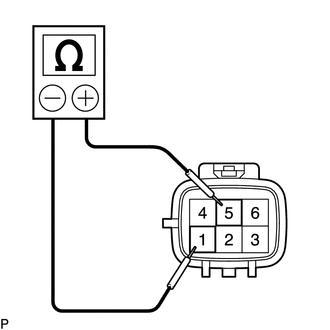
| *1 | Ohmmeter |
| *a | Component without harness connected
(Injector Assembly) |
Measure the resistance according to the value(s) in the table below.
- Standard Resistance:
Tester Connection Condition Specified Condition 5 (CINJ) - 1 (EIJ1) Always 600 to 1400 kΩ 5 (CIN2) - 1 (EIJ2) Always 600 to 1400 kΩ 5 (CIN3) - 1 (EIJ3) Always 600 to 1400 kΩ 5 (CIJ4) - 1 (EIJ4) Always 600 to 1400 kΩ
- HINT:
- ·
If there is an injector assembly that is outside the specified range, only replace that injector assembly.
·Even when the resistance is within the specified range, the injector assembly may be malfunctioning. Therefore, if all of the injector assemblies are within the specified range, replace all of the injector assemblies.
Reconnect the injector assembly connector.
- Result:
Proceed to NEXT
NEXT
Replace the injector assembly.
Click hereEngine / Hybrid System>1KD-FTV FUEL>FUEL INJECTOR(w/ Glow Plug Controller)>REMOVAL
- NOTICE:
- ·
Replace the injector assembly according to the results of the resistance inspection.
·When replacing the injector assembly for a cylinder, always be sure to use a new injection pipe.
·Follow the procedure in the repair manual and temporarily install the injection pipes and nozzle leakage pipe, and then correctly position the injector assemblies. After that, tighten parts according to the torque specifications.
·If the installation procedure is not performed correctly, injector assemblies may become out of position, which may cause the injector assemblies to deteriorate, resulting in malfunctions.
·If an injector assembly deteriorates and malfunctions, other problems such as knocking, rough idle, etc. may occur.
·If an injector assembly becomes out of position, it is possible that the seal between the injector assembly and injection pipe may become incomplete, resulting in a fuel leak.
- Result:
Proceed to NEXT
NEXT
Bleed the air from the fuel system.
Click hereEngine / Hybrid System>1KD-FTV FUEL>FUEL SYSTEM(w/ Glow Plug Controller)>ON-VEHICLE INSPECTION
- Result:
Proceed to NEXT
NEXT
Connect the GTS to the DLC3.
Turn the ignition switch to ON and GTS on.
Clear the DTCs.
Click hereEngine / Hybrid System>1KD-FTV ENGINE CONTROL>ECD SYSTEM(for i-ART)>DTC CHECK / CLEAR
- Powertrain > Engine > Clear DTCs
- 50002 61
Turn the ignition switch off and wait for at least 30 seconds
Turn the ignition switch to ON for 3 minutes or more.
Turn the GTS on.
Enter the following menus: Powertrain / Engine / Trouble Codes.
- Powertrain > Engine > Trouble Codes
- 50001 61
Confirm that the DTC is not output again.
- Result:
Proceed to NEXT
NEXT