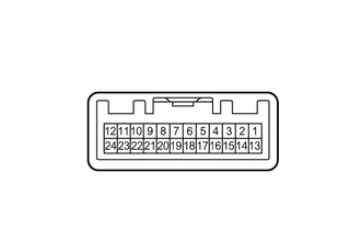
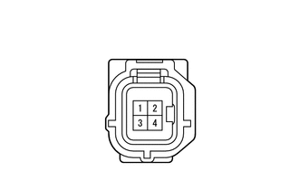
Home › Audio / Visual / Telematics › PARK ASSIST / MONITORING › REAR VIEW MONITOR SYSTEM(for Radio and Display Type) › from 2013.10
RM1840EF _56 Audio / Visual / Telematics _009633 PARK ASSIST / MONITORING _0052662 REAR VIEW MONITOR SYSTEM(for Radio and Display Type) J

PARK ASSIST / MONITORING  REAR VIEW MONITOR SYSTEM(for Radio and Display Type)  Display Signal Circuit between Radio and Display Assembly and Television Camera Assembly  


DESCRIPTION

The display signal from the rear television camera assembly transmits to the radio and display receiver assembly.

WIRING DIAGRAM
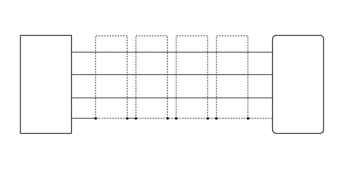
E275627
5.594,2.802 6.208,3 0.615,0.198 10 false G158 5.594,2.979 6.969,3.417 1.375,0.438 10 false Radio and Display Receiver Assembly 5.729,1 6.344,1.198 0.615,0.198 10 false CA+ 5.74,1.458 6.354,1.656 0.615,0.198 10 false V+ 5.75,1.958 6.365,2.156 0.615,0.198 10 false V- 5.74,2.375 6.354,2.573 0.615,0.198 10 false CGND 1.125,1.01 1.469,1.208 0.344,0.198 10 false CB+ 1.125,1.438 1.5,1.646 0.375,0.208 10 false CV+ 1.135,1.948 1.479,2.125 0.344,0.177 10 false CV- 1.021,2.375 1.479,2.583 0.458,0.208 10 false CGND 0.427,2.813 1.042,3.01 0.615,0.198 10 false M2 0.427,3.01 1.802,3.448 1.375,0.438 10 false Rear Television Camera Assembly 2.292,2.531 2.479,2.729 0.188,0.198 10 false * 3.125,2.531 3.313,2.729 0.188,0.198 10 false * 3.99,2.552 4.177,2.75 0.188,0.198 10 false * 4.833,2.542 5.021,2.74 0.188,0.198 10 false * 2.219,3.49 3.521,3.698 1.302,0.208 10 false *: Shielded 5.427,0.875 5.646,1.073 0.219,0.198 10 false 11 5.427,1.344 5.646,1.542 0.219,0.198 10 false 12 5.448,1.844 5.667,2.042 0.219,0.198 10 false 24 5.448,2.24 5.667,2.438 0.219,0.198 10 false 23 1.552,0.885 1.771,1.083 0.219,0.198 10 false 4 1.552,1.344 1.771,1.542 0.219,0.198 10 false 2 1.552,1.813 1.771,2.01 0.219,0.198 10 false 1 1.563,2.25 1.781,2.448 0.219,0.198 10 false 3

PROCEDURE

1.CHECK HARNESS AND CONNECTOR (RADIO AND DISPLAY RECEIVER ASSEMBLY - REAR TELEVISION CAMERA ASSEMBLY)
a.

Disconnect the G158 radio and display receiver assembly connector.


b.

Disconnect the M2 rear television camera assembly connector.


c.

Measure the resistance according to the value(s) in the table below.

Standard Resistance:
Tester Connection Condition Specified Condition
G158-11 (CA+) - M2-4 (CB+) Always Below 1 Ω
G158-12 (V+) - M2-2 (CV+) Always Below 1 Ω
G158-23 (CGND) - M2-3 (CGND) Always Below 1 Ω
G158-24 (V-) - M2-1 (CV-) Always Below 1 Ω
G158-11 (CA+) - Body ground Always 10 kΩ or higher
G158-12 (V+) - Body ground Always 10 kΩ or higher
G158-23 (CGND) - Body ground Always 10 kΩ or higher
G158-24 (V-) - Body ground Always 10 kΩ or higher


Result:
Proceed to
OK
NG


OK

2.INSPECT RADIO AND DISPLAY RECEIVER ASSEMBLY

NG

REPAIR OR REPLACE HARNESS OR CONNECTOR

2.INSPECT RADIO AND DISPLAY RECEIVER ASSEMBLY
a.
E275624
1.521,0.49 1.979,0.76 0.458,0.271 0.583,1.875 0.792,1.875 0.792,1.875 1.042,1.427 true 1.396,1.865 1.26,1.865 1.26,1.865 1.167,1.406 true 0.083,0.104 0.396,0.302 0.313,0.198 10 false *a 1.448,1.771 1.927,1.969 0.479,0.198 10 false CGND 0.365,1.771 0.646,1.958 0.281,0.188 10 false V- 1.563,0.552 2.042,0.75 0.479,0.198 10 false G158
*a Component without harness connected
(Radio and Display Receiver Assembly)


Disconnect the G158 radio and display receiver assembly connector.


b.

Measure the resistance according to the value(s) in the table below.

Standard Resistance:
Tester Connection Condition Specified Condition
G158-23 (CGND) - Body ground Always Below 1 Ω
G158-24 (V-) - Body ground Always Below 1 Ω


Result:
Proceed to
OK
NG


OK

3.CHECK RADIO AND DISPLAY RECEIVER ASSEMBLY

NG

REPLACE RADIO AND DISPLAY RECEIVER ASSEMBLY

3.CHECK RADIO AND DISPLAY RECEIVER ASSEMBLY
a.
E227664
1.5,0.25 1.927,0.521 0.427,0.271 1.833,1.406 2.292,1.708 2.292,1.708 2.49,1.708 true 1.563,1.406 1.115,1.708 1.115,1.708 0.917,1.708 true 1.625,0.302 1.917,0.49 0.292,0.188 10 false M2 0.042,0 0.271,0.167 0.229,0.167 10 false *a 2.552,1.625 2.865,1.792 0.313,0.167 10 false CB+ 0.479,1.625 0.917,1.792 0.438,0.167 10 false CGND
*a Front view of wire harness connector
(to Rear Television Camera Assembly)


Disconnect the M2 rear television camera assembly connector.


b.

Measure the voltage according to the value(s) in the table below.

Standard Voltage:
Tester Connection Switch Condition Specified Condition
M2-4 (CB+) - M2-3 (CGND) Ignition switch ACC 5.5 to 7.05 V


Result:
Proceed to
OK
NG


OK

4.CHECK REAR TELEVISION CAMERA ASSEMBLY

NG

REPLACE RADIO AND DISPLAY RECEIVER ASSEMBLY

4.CHECK REAR TELEVISION CAMERA ASSEMBLY
a.

Using an oscilloscope, check the waveform
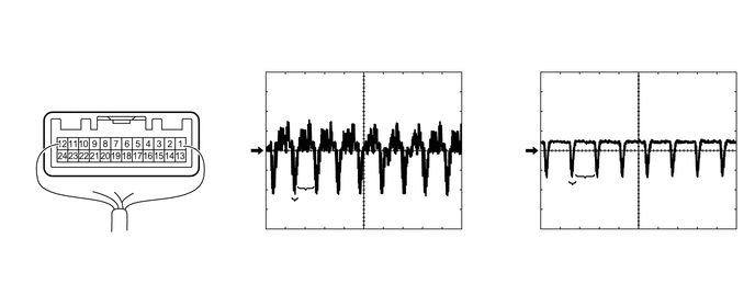
E275625
0.906,0.688 1.385,0.969 0.479,0.281 0.583,1.49 0.531,2.031 0.531,2.031 0.438,2.031 true 0.583,1.333 0.5,0.781 0.5,0.781 0.406,0.781 true 2.792,1.896 2.729,2.469 2.729,2.469 2.635,2.469 true 2.906,1.792 3.063,2.479 3.063,2.479 3.177,2.479 true 5.427,1.74 5.375,2.365 5.375,2.365 5.281,2.365 true 5.552,1.688 5.708,2.375 5.708,2.375 5.823,2.375 true 2.031,1.354 2.479,1.552 0.448,0.198 10 false GND 0.167,0.698 0.458,0.896 0.292,0.198 10 false V+ 0.24,1.948 0.51,2.135 0.271,0.188 10 false V- 0.073,0.083 0.521,0.281 0.448,0.198 10 false *a 4.625,1.365 5.073,1.563 0.448,0.198 10 false GND 2.24,0.354 2.688,0.552 0.448,0.198 10 false *b 0.99,0.75 1.438,0.948 0.448,0.198 10 false G158 4.854,0.354 5.302,0.552 0.448,0.198 10 false *c 2.427,2.375 2.875,2.573 0.448,0.198 10 false *d 3.26,2.406 3.708,2.604 0.448,0.198 10 false *e 5.083,2.281 5.531,2.479 0.448,0.198 10 false *d 5.865,2.302 6.313,2.5 0.448,0.198 10 false *e
*a Component with harness connected
(Radio and Display Receiver Assembly)
*b Waveform 1
*c Waveform 2 *d Synchronized Signal
*e Video Waveform - -


Measurement Condition
Item Content
Tester Connection G158-12 (V+) - G158-24 (V-)
Tool Setting 0.2 V/DIV., 50 μs/DIV.
Condition Waveform 1: Ignition switch ON, shift lever in R
Waveform 2: Ignition switch ON, shift lever in R, screen blacked out by covering camera lens

OK:

Waveform is as shown in illustration.


HINT:

The video waveform changes according to the image sent by the rear television camera assembly.


Result:
Proceed to
OK
NG


OK

NG

REPLACE REAR TELEVISION CAMERA ASSEMBLY